I have been experimenting with getting the Minicube64 running on the Raspberry Pi Pico. I’ll talk more about that another time, but today I’ll cover one part which was seemingly simple but caused me a few headaches along the way - reading a Sega Mega Drive pad. The Minicube64 has support for a 3 button pad with directional controls, so the Mega Drive pad is ideal here.
The Sega Mega Drive originally shipped with a 3 button controller, it had the standard UP, DOWN, LEFT, RIGHT switches as well as buttons A, B, C and START. It has a standard DB-9 connector so seemed quite simple to interface with - after all I did explore how the Kempston Joystick interface was put together.
The Protocol
Unlike the Kempston, the Mega Drive has too many buttons to fit into the DB9 connector. As a result, there is a simple protocol to access it.
Rather than reverse engineer it myself, I used the excellent description from Jon Thysell.
| Select (Pin 7) | Pin 1 | Pin 2 | Pin 3 | Pin 4 | Pin 6 | Pin 9 |
|---|---|---|---|---|---|---|
| LOW | * | * | A | START | ||
| HIGH | UP | DOWN | LEFT | RIGHT | B | C |
Basically, you have to perform two reads from the controller to get the state. The first read has the SELECT line HIGH to read the UP, DOWN, LEFT, RIGHT, B and C buttons. The second read is done with the SELECT line LOW to pick up the A and START button.
Side note: I find it a little strange that the
HIGHstrobe maps in B and C rather than A and B
The six button pad has a different protocol (but is still compatible with the original), but I won’t cover that here.
The ideal target would be end up with a bit pattern for each strobe:
| 7 | 6 | 5 | 4 | 3 | 2 | 1 | 0 |
|---|---|---|---|---|---|---|---|
| X | X | C | B | RIGHT | LEFT | DOWN | UP |
| X | X | START | A | * | * | X | X |
The two * are always low and can be used to detect the presence of a controller when querying he controller with SELECT pulled LOW. This could be pretty handy as a check.
Wiring up to a Pico
The first thing to be aware of is that the Mega Drive controller is a 5V device and the Pico is a 3.3V device. This means that you can’t just connect the output pins from the controller to the Pico, you need to level shift them.
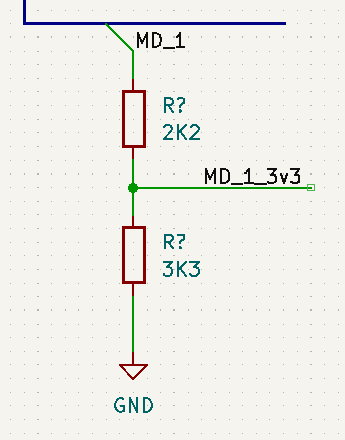
For this I chose to use my standard approach using a voltage divider; use a 2k2 resistor on the signal line and a 3k3 resistor to pull to ground.
I pulled the SELECT line to +5V for this test as I didn’t want to worry about having to strobe the line for now.
When reading the signals from the Pico I found that the UP and DOWN were always being pulled to ground and therefore being registered as “pressed”.
I hunted around for a schematic of the pad and found that GameSX came to the rescue.
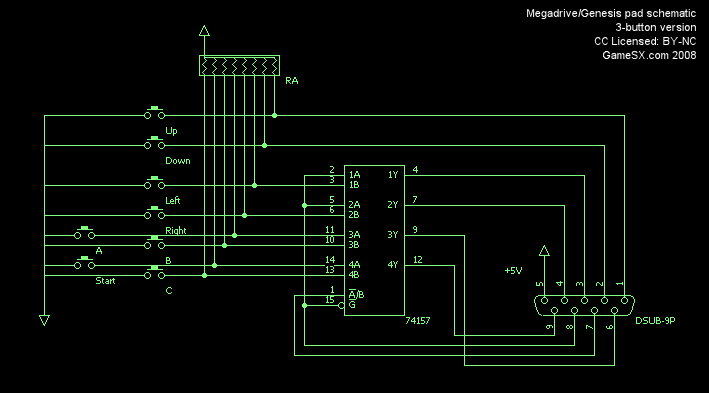
This image is Copyright GameSX and is distributed under the CC-NC-SA-4.0 terms
The buttons UP and DOWN are the only two connected directly via pull-ups to 5V. I opened up my Mega Drive pad and confirmed that the internal pull-ups are all 10K and that the schematic there is sound.
To figure out what was happening, you have to dig into how all these resistors affects the total circuit.
The resistors involved in the voltage divider circuit are acting as a stronger pull than the 10K pullup, which means that a high logic level is still LOW.
I changed this to 3K3 and 6K8 and the Pico could read it.
However looking at the simulation of this, it’s barely under 1.7V which is probably at the edge of tolerance for the Pico’s GPIO (which states logic HIGH is at 2V, but could be around 1.8V). Better values for these resistors would be 6K8 and 13K6 or thereabouts; this would give a logic high of over 2V which is well in the range for the logic HIGH.
This is an interesting lesson; you have to consider the whole circuit when interfacing with external devices.
Finally; why does this affect only the UP and DOWN buttons and not the others? The other signals are driven from the 74xx157 that deal with the SELECT line switching; I suspect that they’re driven enough so that the voltage divider resistors don’t pull them to ground.
SELECT line shenanigans
Remember I said I pulled the SELECT line HIGH for the tests? The next stage of fun came to actually using it for real.
After connecting the SELECT output to the Pico, I got what looked like a floating behaviour on the line when the logic level was HIGH. Opening up the controller it confirmed my suspicion, the 74xx157 inside is a HC variant, a CMOS 5V part.
The logic levels for CMOS 5V are 3.6V HIGH - well above my 3.3V pico levels. I needed to boost it to 5V.
Side note: Normally when shifting from 3.3V to 5V TTL/HCT, the logic levels are fine as TTL has a lower
HIGHthreshold, but because this is a HC part, the levels are very different.
Boosting 3.3V to 5V is not something I’ve done before, so I had to explore the options.
Microchip published a document of 3V tricks and tips that describe some of the approaches.
These are basically:
- Diode offsets
- Dual NPN transistors with pullups to each level
- MOSFET based solution
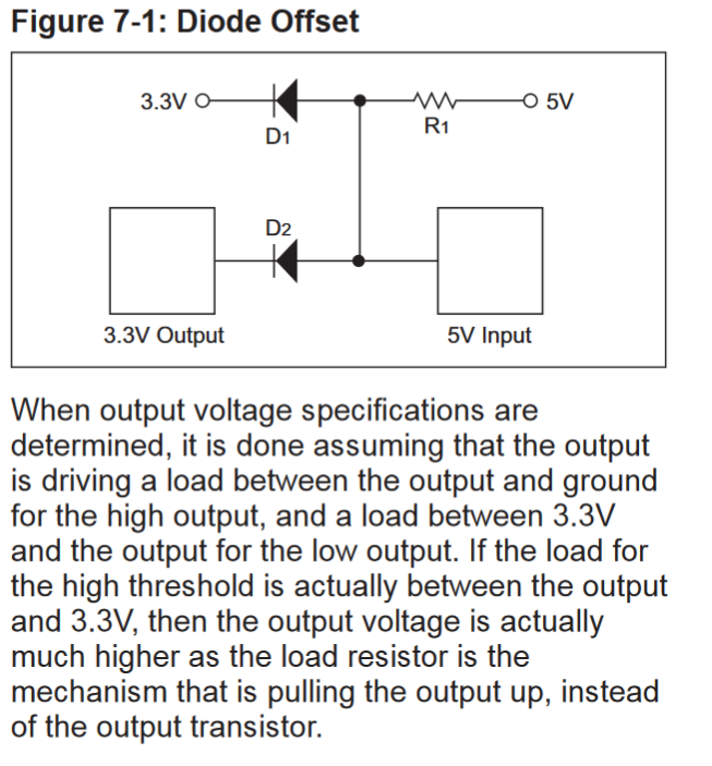
I simulated a few of these on the Falstad sim:
For some reason I couldn’t get any of these approaches working reliably. I even tried using an NPN transistor based inverter which should boost the signal to 5V (albeit inverting it), but didn’t get a good signal from that.
I ended up using a MOSFET-based bi-directional shifter board that are widely available and that did the trick.
I’m going to keep trying on the simpler approaches, as they should work, so I assume I did something wrong.
Pico code
The last thing to talk about is the code to actually read the controller. During testing I was using the gpio libraries in the Pico SDK, however there’s something to consider - the hold times of the SELECT line before the outputs from the pad become valid. The
datasheet for the 74HC157 indicates that a propagation delay of 20ns is reasonable, which means that on the Pico we have to artificially delay between setting the SELECT line and reading the pins.
I decided to move the code into the PIO and have it continuously read and push the state of the controller back to the system. The hold time was dealt with by using “sticky” outputs and holding the pio with a few NOP cycles.
    .program controller
    .wrap_target
        mov pins,!null  [31]    ; SELECT line HIGH
        nop             [31]    ; hold
        in pins,8       [31]    ; read pins (UDLRBC)
        mov pins,null   [31]    ; SELECT line LOW
        nop             [31]    ; hold
        in pins,8       [31]    ; read pins (A/Start)
        push noblock
    .wrap
Doing this via PIO is convenient as you get a 16-bit value in the RX buffer with the state of both strobes. I can just sample this buffer and pull the latest value.
    enum md_controller_buttons {
        MD_CONTROLLER_NONE = 0,
        MD_CONTROLLER_UP = (1 << 0),
        MD_CONTROLLER_DOWN = (1 << 1),
        MD_CONTROLLER_LEFT = (1 << 2),
        MD_CONTROLLER_RIGHT = (1 << 3),
        MD_CONTROLLER_B = (1 << 4),
        MD_CONTROLLER_C = (1 << 5),
        MD_CONTROLLER_A = (1 << 6),
        MD_CONTROLLER_START = (1 << 7),
    };

    unsigned int pins = MD_PIO->rxf[MD_SM];

    uint8_t a = (~(pins >> 8)) & 0b00111111;
    uint8_t b = (~pins) & 0b00110000;
    uint8_t result = a
        | ((b & MD_CONTROLLER_BIT_B_A) ? MD_CONTROLLER_A : 0)
        | ((b & MD_CONTROLLER_BIT_C_ST) ? MD_CONTROLLER_START : 0);
I could probably improve this by waiting for IRQ signals and then firing an interrupt back to the main cpu, but for my purposes just reading and pushing the state to the RX buffer is good enough.
Final Wiring
With all this done I ended up with this schematic:
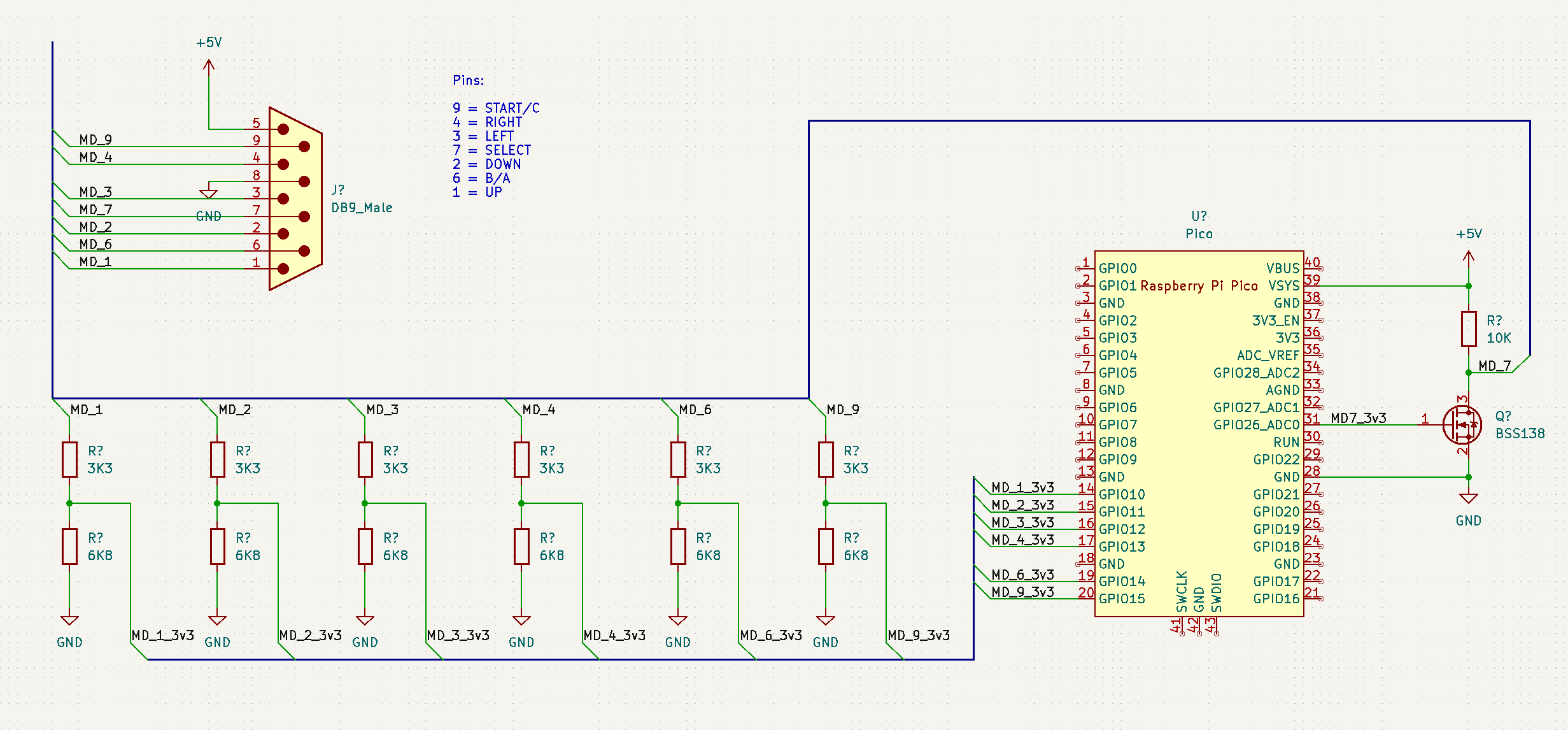 .
.
You can ignore the SELECT line being on an odd pin, it’s because I’m using those for an SD Card so I omitted them here.
I could also have kept the 2K2/3K3 resistors for all but MD_1 ad MD_2 (as these two don’t use the 74HC157) but I figured it’s best to be consistent (I may end up regretting this though!).
Wrap up
What seemed like a pretty simple system turned out to have a couple of surprises along the way. We got there in the end though.
’til next time.
Addendum
I realised after I wrote this post that the 10K pullups in the Mega Drive pad could actually be used to create a voltage divider to drop it to ~3V.
By using a higher resistor value at the bottom of the divider (15K or so) you can drop the 5V to around 3V for use in the Pico.
This should be usable for the UP & DOWN lines, but obviously it’s not suitable on the other lines. It saves needing an extra couple of resistors and simplifies the circuit a little.