After the last post I ended up with a working system that could read the Mega Drive controller from a Raspberry Pi Pico.
 .
.
Job done right? Well, I guess not as here we are again talking about the same subject again - this is a post I wasn’t expecting to write!
Pins, pins, pins
I was working on the Minicube64 project (will save that for another day) and I wanted some more pins for the video driver circuit. However I’d pretty much run out of GPIO on the Pico.
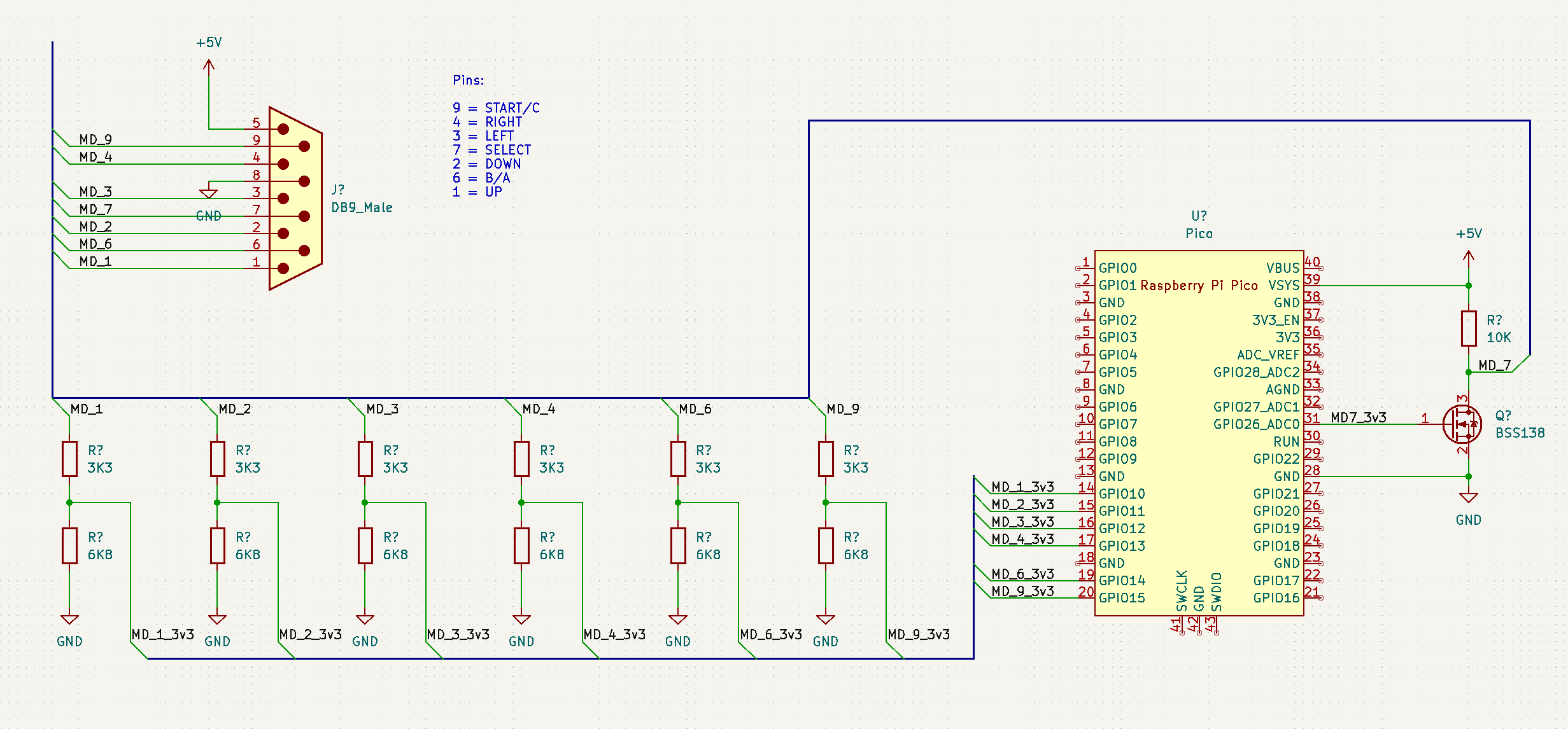
The initial version of the controller interface used 7 GPIO to handle the data pins on the DB-9 connector. I felt I could drop some pins with the help of electronics.
So how, exactly do you drop some pins and still achieve the same functionality?
Enter shift registers.
Feelin’ shifty
In the current setup we sample the controller’s data pins from the Pico’s PIO whenever we need them. As we do several pins at once, we call this parallel loading, it’s simple and ensures that all the pins are captured together in the same instant. It does this at the cost of needing more pins.
The other approach to reading data is serially, eg: one bit at a time. If you’re familiar with protocols like SPI you’re likely aware of this. Each bit is presented to the system one bit at a time and it changes when you clock it. The down side of serial interfaces is that they usually take longer to read 8 bits due to the clocking, as as the data isn’t read at the same instant the state of it can change.
The 74LS165 is a parallel-in, shift-out (or PISO) register. It captures the state of 8 pins in parallel when you load it, after that you can read the data serially via the shift output and clock. This is beneficial to us as it lets us grab the state of the controller as a snapshot and then access it serially.
Using a 75LS165 part means that I can get rid of a lot of the level-shifting resistors I used in the first version, as it’s a 5V TTL part so should interface with the 74HC157 inside the controller itself.
Schematic
 .
.
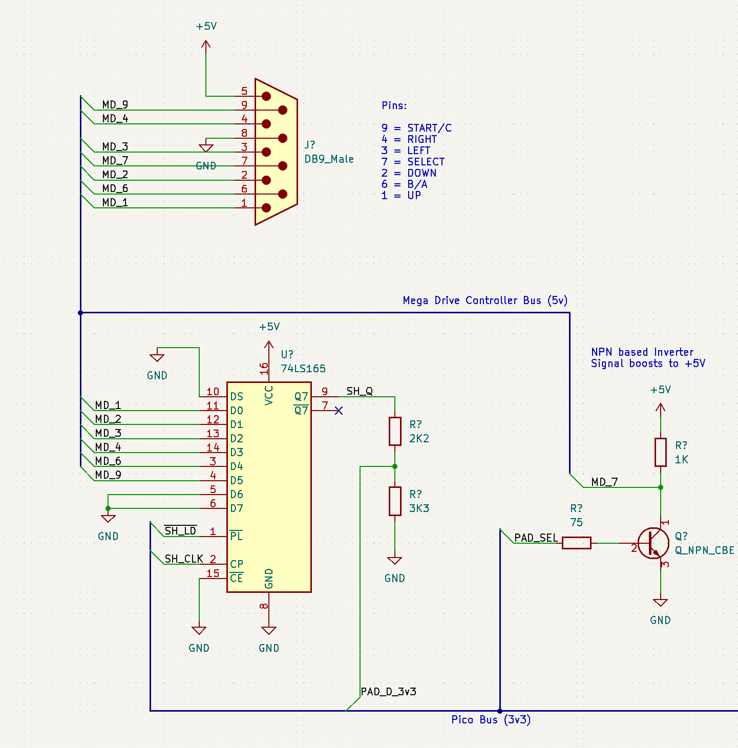
The wiring is pretty simple. The controller button pins are wired directly to the shift register. The output of the shift register is passed through a 2k2/3k3 voltage divider to drop from the 5V logic level to something that won’t fry the Pico.
Side-note: The TTL outputs on the 74LS165 seem to be around 4V, so we could use lower resistor values to voltage drop here.
The next change I made was to use an NPN transistor as a simple booster from the 3V3 logic level to 5V on the SELECT line. I originally tried this out on the first version but couldn’t get it to work. The reason, it turns out, was that the inline 1K resistor was too high, so dropping this to a lower value such as 75R-100R seemed to do the trick. The NPN transistor acts as a switch, but with the effect of inverting the output. I just handled this in the Pio by also inverting the pin.
PIO code
It took a bit of messing to get this right as there’s a few timings at play.
The first is the /LD signal on the 74LS165 needs to be held for approx 35ns, and the CLK needs around 25ns.
The second is that the use of the NPN transistor adds a bit of extra delay for the switching time, so it extended the duration needed for the SELECT line to stabilise and register.
I decided that going with a rule of 4/2/1 for the SELECT, /LD and CLK seemed about right; e.g the SELECT line is held for 4x the duration of CLK.
The final part of the timings was that in my last code I was artificially lengthening each PIO instruction; this time around I set the clock divider to 32, meaning it runs at approx 8Mhz (which is still pretty fast and could probably be dropped). Testing seemed to show these numbers were responsive enough though.
    .program md_controller_s
    .side_set 2
    .define NONE    0
    .define CLOCK   1   ; active high
    .define LOAD    2   ; active low (inverted by config)
    .wrap_target
        ; SELECT HIGH = pins U,D,L,R,B,C
        set pins,1      side NONE [4]

        ; LOAD (and hold)
        set Y,7         side LOAD [2]   ; parallel load
        nop             side CLOCK      ; clock the first value in
    loop_h:
        in pins,1       side NONE
        jmp Y--,loop_h  side CLOCK

        ; SELECT LOW = pins START,A
        set pins,0      side NONE [4]

        ; LOAD (and hold)
        set Y,7         side LOAD [2]   ; parallel load
        nop             side CLOCK      ; clock the first value in
    loop_l:
        in pins,1       side NONE
        jmp Y--,loop_l  side CLOCK

        push noblock    side NONE
    .wrap
I’m using side-set pins mapped to /PL and CLK, the SELECT line is mapped to the normal set pins. Finally, the Q value from the shift register is mapped to the in pins.
The use of the loop counters and side-set pins allows me to pull all 8 bits from the shift register and clock it at the same time. The output is the same, at the end of the code the 16-bit value is push to the RX fifo buffer to be picked up in the same format as the first version.
The final piece is to make sure I invert the outputs of the /LD pin in the state machine setup, so that when I set it high in the PIO code, it actually drives it low. It makes it easier to deal with when using side-set.
Wrap up
And that’s it; by using the shift register I can read the controller using 4 GPIO, freeing up 3 pins for other use. That’s a nice saving!
TTL