Kempston Joystick Interface Stripdown
One thing you seem to accumulate a lot of when acquiring ZX Spectrums is a variety of peripherals. Joystick interfaces, in particular, are one that seem to turn up tim and time again.
I was recently sorting through them to find a working one to send over to @breakintoprog and one I tested was broken.
This is a post about me stripping it down and figuring out what makes it tick.
ZX Spectrum Joystick Interfaces
If you wanted to use a joystick with a Spectrum you had to buy an add-on joystick interface. These connected to the edge connector at the back of the machine and featured one or more Atari 9-pin joystick ports on them.
The Spectrum had a few competing joystick standards at the time. We had the Protek/AGS “cursor” type that mapped its inputs to the cursor keys and the Kempston standard which went a different path. There were also “Fuller” and “Programmable” types, but I don’t remember those being as common.
Sinclair released the “Interface 2” which mapped its inputs to the number keys but also had a different port wiring, making the actual joysticks themselves incompatible with the Atari 9-pin standard that other platforms supported. It wasn’t until Amstrad released the +2 that the Spectrum came with an in-built set of joystick ports at all.
Generally a game for the Spectrum would end up supporting Cursor, Kempston and “redefinable keys” out the box. This latter option made it possible for us humble Sinclair owners to actually use our crappy Sinclair joysticks (seriously, have you ever used one of those things?!).
The Kempston Standard
One thing that makes the Kempston standard appealing to us Z80 assembly programmers is that it is extremely easy to work with. You issue a single IN to port $1F and read a byte back with the form 000FUDLR (active bit high).
Other standards required checking multiple ports that were associated with the keyboard (hence them being key mappable). The latter made it easier for BASIC programmers or people who wished to use the “redefine keys” options in games - this simply wasn’t possible with a Kempston joystick.
Just knowing this tells us a little about the hardware itself.
- It responds only to an I/O READ on port $1F
- It does not respond to memory reads, writes or I/O WRITEs to the port.
- It uses 5 bits, so it must use 5 data lines on the edge connector
- It bits as HIGH when an action is set, thus the default state for each bit is LOW
Kempston Teardown
Having a broken Cheetah interface that was known to be Kempston compatible and an afternoon on my hands, I decided to try my first reverse engineering of the hardware.
Note; this has been done many times by many people, so there’s really nothing “new” to be learned by the community. However it’s my first time trying something like this; and having not yet read/watched an existing teardown, I was able to approach it without outside influence.
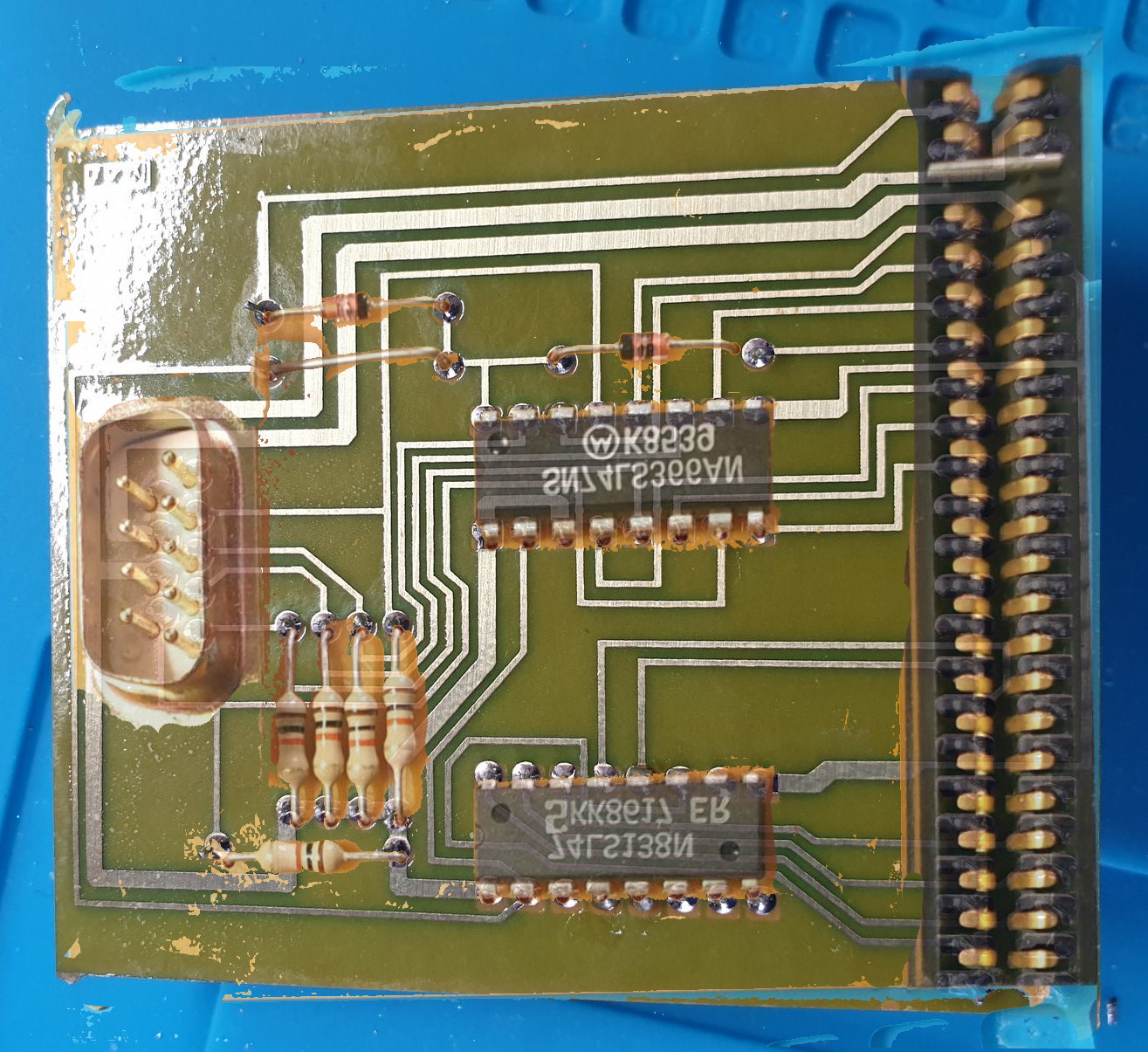
The PCB
The case was a bit fiddly to open, it was clipped in plastic (no screws), but when I popped it open I saw this.
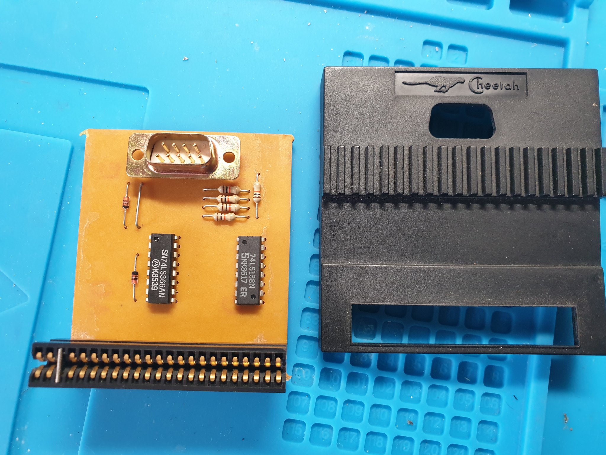
Here we have:
- 9-pin “Atari” joystick port
- 74LS366 logic IC
- 74LS138 logic IC
- 2x diodes
- 5x resistors
- 1x jumper wire
- 1x edge connector
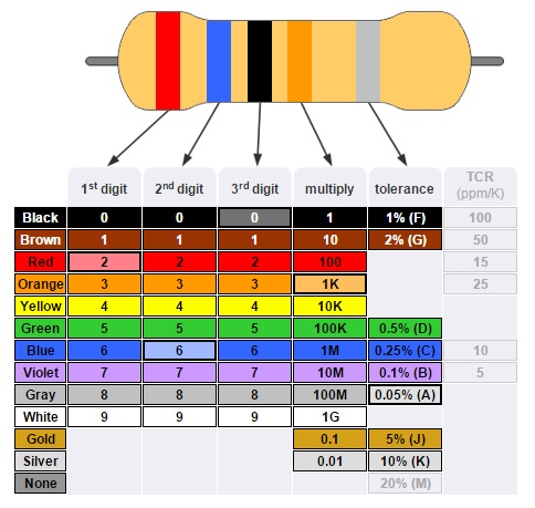
When you check the colour codes:
    Brown  = 1
    Black  = 0
    Orange = x 1k
           = 10K
I’m terrible at decoding the colour bands on the resistors, so I measured them with my multimeter - they all came out as 10K, which is what the code says.
As there’s 5 of them and they’re all high resistance levels, it’s pretty easy to deduce that they’re used as pull-up or pull-down resistors for each of the 5 inputs. We’ll check this a bit later as we go further.
Flipping it over we see:
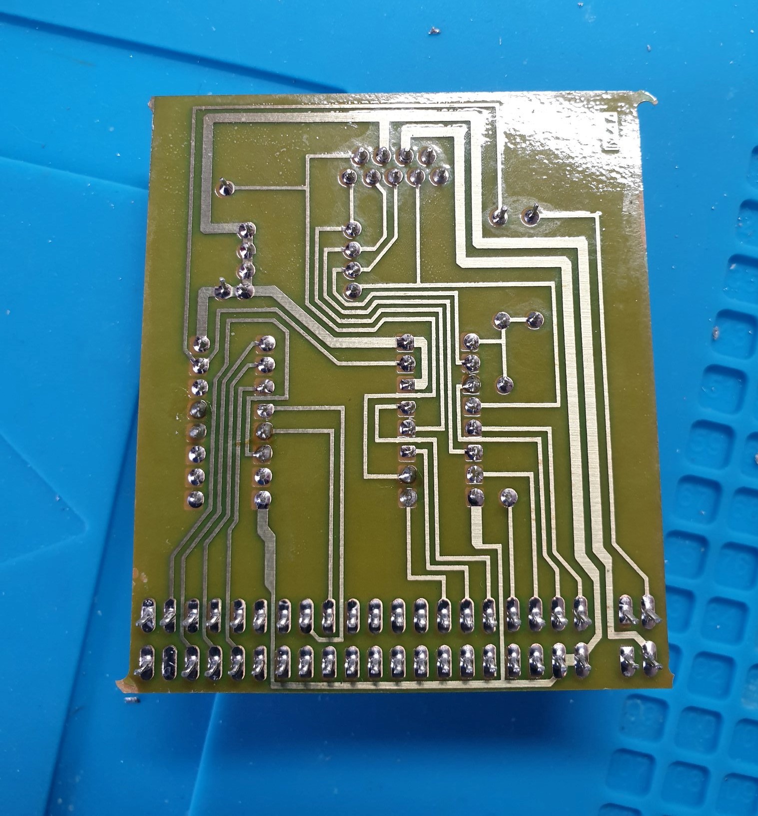
Just a mess of traces - we’ll decode all that shortly.
The ICs
The two integrated circuits on the board are a 74LS366 and a 74LS138.
Looking up the datasheets tells us this:
- 74LS138: “One-of-8 line decoder/demultiplexer”
- 74LS366: “Tri-state line driver/buffer with inverter”
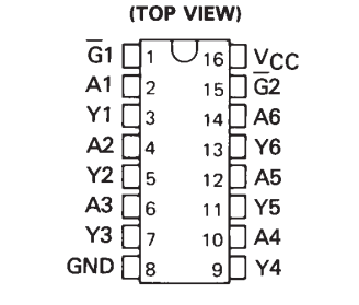
74LS138
Here’s the pin out of the 74LS138:
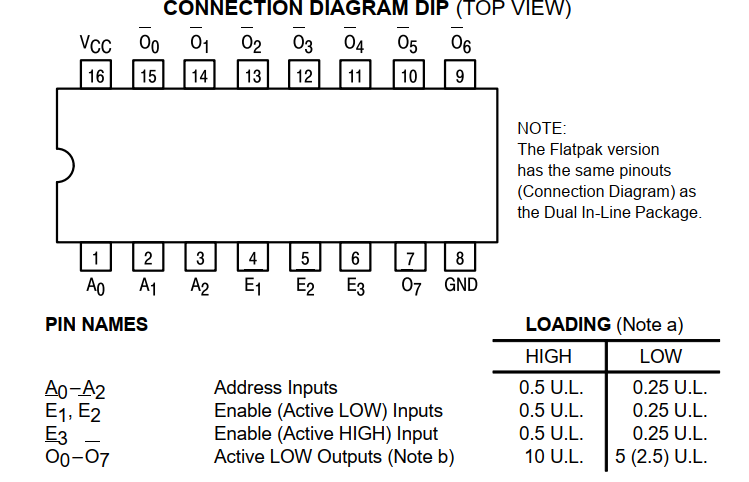
… and the logic diagram:
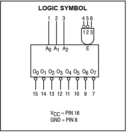
E1, E2 and E3 are part of an AND gate; with E3 being active HIGH. This gate is used to control the ENABLE state of the chip.
We then have 3 bits of (A0-A2) address inputs and 8 bits of output.
Looking at the truth table and the functional description of this chip, it looks like the job is to take the combination of the three enable inputs and the three address bits and output a mutually exclusive bit on the output. The only time the outputs are all the same is when the ENABLE gate condition isn’t being met; in this case the outputs will all be HIGH.
We can early deduce that this chips is likely the one that decodes the IOREQ/READ and the port address; with likely one of the outputs being used to chip select the 74LS366.
74LS366
Here’s the pin out and logic diagram of the 74LS366:
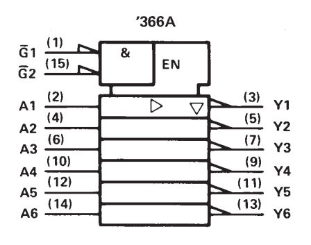
Here we see that the chip has 6 inputs (A1-6) and 6 inverted outputs (Y1-Y6). These are controlled by two active low inputs ~G1/~G2 configured in an AND gate.
This chip is very likely to be the one that handles the input from the joystick, mapping it onto the output data lines of the edge connector if it’s active. This latter point is important, otherwise the joystick would just trash the data lines outside of the IOREQ.
Tracing the, umm, Traces
First up, let’s overlay the front and the back of the PCB.
Here we see that the 74LS138 is at the “bottom” of the board and the 74LS366 is the one sat in the middle. The resistors are connected to the joystick port pins and one of the pins on the 74LS138.
Based on what we already learned from the datasheet on the 74LS138, we can speculate that this could be one of the ENABLE gate inputs.
Using a paint program, I started annotating the traces and some of the pins.
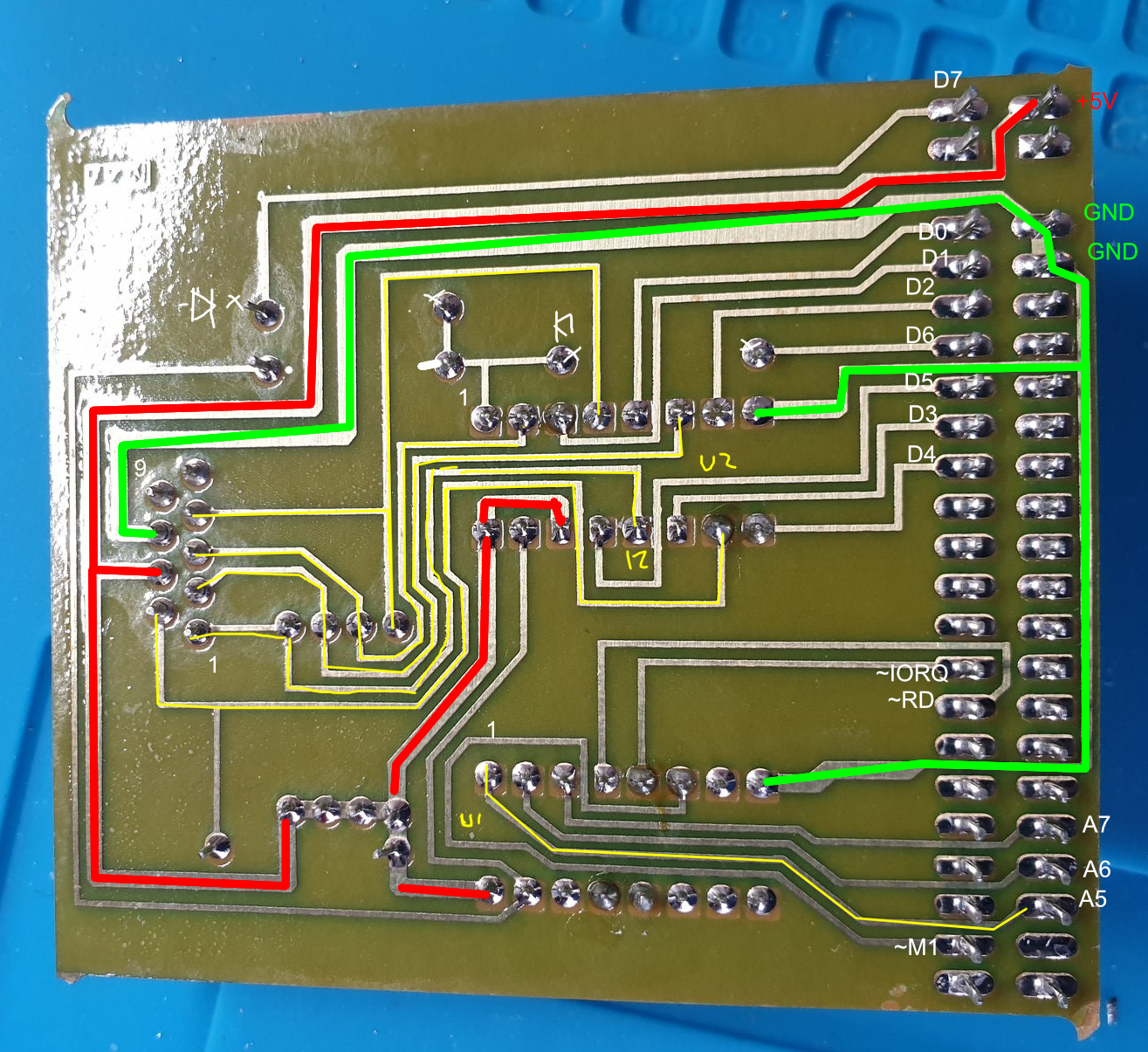
This is beginning to tell us a great deal already!
We now know that it’s using address bits A5-7 on the expansion, involves ~IOREQ & ~RD and ~M1 for control and touches all of the 8 data bits.
When we turn the port address $1F to binary we get:
    7 6 5 4 3 2 1 0
    0 0 0 1 1 1 1 1 = $1F
It’s an inversion of the bits 7, 6 and 5 - these are exactly the address bits that have connections on the expansion bus!
Looking at the data lines here we can see that D0-5 are connected directly to the 74LS366; D6 and D7 are connected to the anode (+ve) end of diodes.
The other main inputs of the 74LS366 are connected to the 9-pin Atari socket but appear to have pull up resistors too. At this point, I’m speculating that the resistors are there to keep the inputs pulled high instead of floating; inputs on those pins pull them low, and these are then inverted by the 74LS366 to form the ---FULDR bit pattern we see on the Spectrum.
Schematic
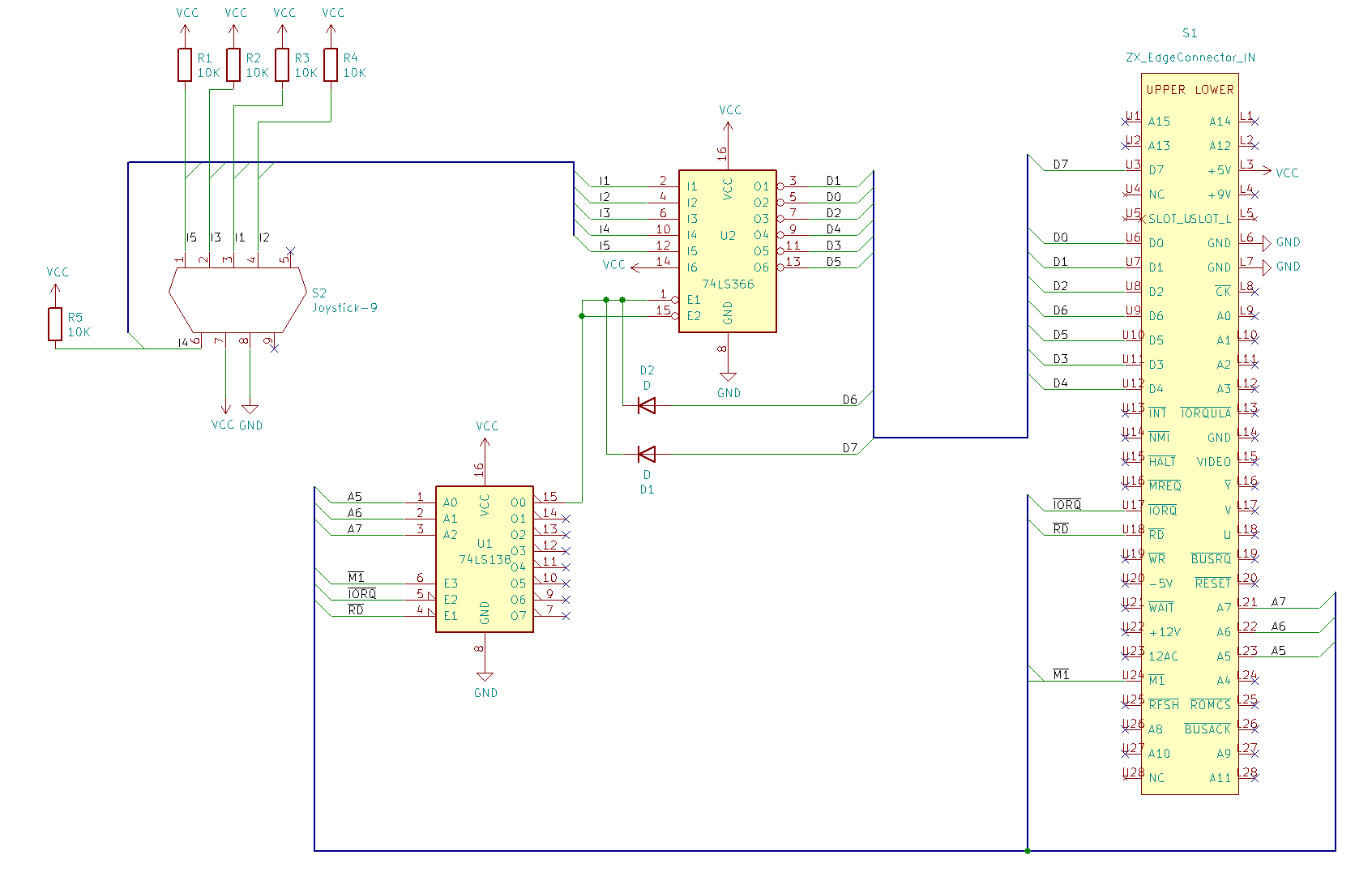
At this point, I started out with KiCad and mapping out the various bits I knew. With the datasheet at hand, I ended up with this:
 .
.
I’m still learning all this stuff, so it may not be correct.
How I interpret all this is that:
- 5 of the the 9-pin Atari inputs are connected to the 74LS366 via a series of pull up resistors
- The 6th input of the 74LS366 is pulled high
- The 74LS366 inverts the inputs, meaning D5 is always low
- The 74LS366 enable/chip select is controlled by the 74LS138
If you remember from before, the 74LS138 enables exactly one output for a given combination. Only pin 15 is wired up, so we have to look at the conditions that will set that from the datasheet.
The datasheet says:
    A0, A1, A2 must be LOW
    E1, E2 must be LOW
    E3 must be HIGH
The A input pins are connected to A5, A6, A7 on the address bus, which we have already determined to be the pins we are interested in. This means that the interface will only be active when these lines are all low. I wonder if that means we can read the joystick from any port, as long as the A5-7 pins are low? Might be something worth testing.
The E1 & E2 pins are connected to ~RD and ~IOREQ, which we know are active low. This would mean that E3 (~M1) needs to remain high for the combination to trigger.
I will need to read more about the M1 line on the Z80 to fully understand it, but from a quick look it appears to be driven by the ULA. Whilst high (and with IOREQ active) it means we’re in a PIO routine; driving this low without RD/IOREQ indicates a reset of the PIO. This makes sense in this circuit, as it’s essentially saying “when in the middle of an READ IOREQ, activate the 74LS138”.
All of this means, in laymans terms:
When an READ IOREQ occurs on port $1F, activate the circuit which takes the joystick inputs and map them onto the data lines D0-D4.
Which is exactly what we expect to happen from using it!
Summary
This is quite an elegant little circuit that involves a couple of simple ICs and some simple, yet clever logic to achieve a joystick input.
It was a lot of fun to go through this and reverse engineer it myself. I’ve never done something like this before, so it as a huge learning experience for me overall.
To make sure I haven’t got my interpretation incorrect, I had a look at Old Machinery’s blog on the subject. I am pleased to say that it pretty much tallies up with that interpretation too.
Perhaps I’ll have a go at building this circuit myself on a breadboard :)
Until next time, thanks for reading!