Last time I talked about my project to create an Interak-like VDU for my Z80-based breadboard computer (which is based on the RC2014 bus); we ended up with a working character based monochrome composite display. There’s a little more to do, such as making the display support programmable graphics from the user, but before we do that I’m going to look at a different aspect.
This time around I want to talk about adding keyboard support to the system which would make the machine fully interactive from the outside. Being able to enter text and see it on a screen is something that makes a computer “real” to me so it’s something I’d love to achieve.
Interak Keyboards
It’s worth discussing how the Interak handles keyboard input, as that’s what I’d like to reproduce. The Interak used an ASCII parallel keyboard which was connected via a card the user would install. This card essentially took the key presses from the keyboard, latched them and presented an I/O port for the system to read.
The I/O port is typically exposed as $40 (fully decoded, but 8-bit), however like everything to do with the Interak, the user could change the I/O port mapping with DIP switches. Most software I’ve seen uses $40, so that appears to be the common value.
There’s quite a bit of electronics on the LPK1 Interak keyboard card, and much of it seems to be down to the latching and I/O wait state handling. I’m not going to bother much with that in my implementation.
The Interak continuously polls port $40 for a value; if it sees a value with bit 7 set it treats it as a valid key press and deals with it. If bit 7 is not set, the key is ignored.
Basic Operation
Let’s look at what we roughly need to achieve then:
- USB keyboard handling on the Pi Pico; detect a keyboard, detect a key press (including shift & control modifiers)
- Detect an IO read from Z80 bus at port
$40 - Respond to that read with the last key pressed on the USB keyboard
- If no key was pressed, keep bit 7 low
- If a key was pressed, set bit 7 high
There’s a couple of ways to tackle this; the first would be to decode the port in TTL electronics and signal the Pico like I did with the VRAM writing. The second would be to allow the Z80 to signal the Pico and have the Pico decode the port. Stupidly, I decided on the latter as I figured that it might be nice to try this and maybe handle more ports in the future (programmable graphics being an example).
USB Keyboard reading
You’d think this would be easy, but it wasn’t - and it was entirely for dumb reasons.
It’s relatively simple in principle; hook up the tinyusb config and handlers and then go. This is much more annoying than it initially seems, largely because the docs and examples aren’t great.
So I’ll save you some trouble. What you’re looking at is setting the Pico up as a USB host. Not a hub. Not a device. A host. Got that? Good.
I decided to set it up on RHPORT1; I think it will work on RHPORT0 but I spent so long trying to get this to recognise a keyboard that I stopped configuring it once it worked.
#define CFG_TUSB_RHPORT0_MODE       OPT_MODE_NONE
#define CFG_TUSB_RHPORT1_MODE       OPT_MODE_HOST
To initialize the host, make sure you call tusb_init(); on start up and then poll tuh_task(); on a regular basis. You also need to implement some callbacks to handle the various device reports; much of what I have is based on
picoterm key handling code, which in turn is based on the
pico-examples project so either of these are probably the best thing to look at.
Once you have this configured I also recommend you set up a blinking LED to signal when it’s not detected the keyboard. You can turn it on or off permanently when it’s connected, but I definitely recommend this as it will save you pain.
The final thing to talk about is something that caught me out. Make sure you connect +VSYS on the Pico to the 5V on the Z80 bus. This is what actually powers the keyboard, and without it you will not get a detection. I spent literally HOURS on this until I stumbled across a random forum post mentioning it.
Whilst you’re there, it’s probably best to hook up +VBUS on your Pico to the same 5V line, but do it via a schottky diode. This will allow you to connect your PC’s USB to the Pico whilst the main Z80 machine is powered on.
I/O port handling
Until now the Pico has been a passive bus participant. It’s watched data come in, but not sent anything back. This is about to change.
First up; I decided to use another 74LS138 to turn the /IORQ, /RD and /WR signals into simple /IORD and /IOWR signals.
                        74LS138

                  -------\___/-------
         /WR    A |  1           16 | VCC   (5V)
                  |                 |
         /RD    B |  2           15 | Y0
                  |                 |
         GND    C |  3           14 | Y1   /IORD
                  |                 |
      /IORQ  /G2A |  4           13 | Y2   /IOWR
                  |                 |
      /IORQ  /G2B |  5           12 | Y3
                  |                 |
         VCC   G1 |  6           11 | Y4
                  |                 |
               Y7 |  7           10 | Y5
                  |                 |
              GND |  8            9 | Y6
                  -------------------
Largely because it was easy to do; but ultimately it meant I had to do less work on the Pico side. I may have been able to reuse the one I set up for the VRAM, I haven’t really checked.
This gives me the PIN mappings of:
                       PI PICO
                 -------\___/-------
       SYNC  GP0 |  1           40 | +VBUS
                 |                 |
       LUMA  GP1 |  2           39 | +VSYS
                 |                 |
             GND |  3           38 | GND
                 |                 |
    VRAM_WR  GP2 |  4           37 | 3V3_EN
                 |                 |
        A00  GP3 |  5           36 | +3V3
                 |                 |
        A01  GP4 |  6           35 | ADC_VREF
                 |                 |
        A02  GP5 |  7           34 | GP28  NC
                 |                 |
             GND |  8           33 | GND
                 |                 |
        A03  GP6 |  9           32 | GP27  NC
                 |                 |
        A04  GP7 | 10           31 | GP26  /IORD
                 |                 |
        A05  GP8 | 11           30 | RUN
                 |                 |
        A06  GP9 | 12           29 | GP22  D7
                 |                 |
             GND | 13           28 | GND
                 |                 |
       A07  GP10 | 14           27 | GP21  D6
                 |                 |
       A08  GP11 | 15           26 | GP20  D5
                 |                 |
       A09  GP12 | 16           25 | GP19  D4
                 |                 |
       A10  GP13 | 17           24 | GP18  D3
                 |                 |
             GND | 18           23 | GND
                 |                 |
       A11  GP14 | 19           22 | GP17  D2
                 |                 |
        D0  GP15 | 20           21 | GP16  D1
                 -------------------
The first version of my code had the following setup:
- a state machine running on PIO1 that reacted to the GPIO pin for
/IORD - this state machine would sample the address pins
A0-A7and push them - it would fire an IRQ to the system to decode the address, then optionally push data onto the transmit FIFO for a second state machine
- the second state machine is configured with
D0-D7as output pins, but with the pins as inputs - this state machine would set its
pindirstoOUT, send the data and then set thepindirstoIN
The pindirs complexity is new here. The Z80 bus is bidirectional, so we have to be passive (high-Z) until we’re expected to assert a value.
I set the Z80’s ROM up to continuously poll port $40 and then print a message to the screen Key: X with the key it saw. If it saw no key, then do nothing.
.key_loop:
    nop
    in a,($40)
    bit 7,a
    jr z,.key_loop
    and $7F ; remove high bit
    ld hl,last_key
    ld (hl),a
    ld de,msg_key
    ld bc,$0500
    call printstr
    ld de,last_key
    ld a,(de)
    ld (hl),a
    jr .key_loop


msg_key:
    db "Key: ",0

    ORG $5000   ; this lives in RAM

last_key:
    db 0,0
Bad times
When it came to test this I ended up with… bad things.
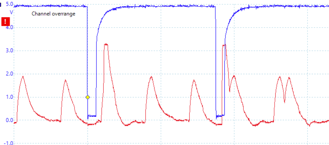
The image shows that the D7 line (red) rises well after the /IORD (blue) falls low. I was basically dumping garbage on the bus well after the I/O request had completed. The results of this could be anything or nothing, depending on what was happening on the system at the time.
It was clear to me that the cycle of PIO->ARM CPU->PIO was far too slow to run at the 4Mhz system clock of the Z80. I had to rethink the problem.
The question is “can we do all of this in PIO, and not call back to the ARM?”. I scratched my head on this a lot and figured out that I could do it in a single PIO state machine too, but it takes a couple of tricks.
Port decode in the PIO
The first problem is that of address decoding. How do you do this in the PIO when you have no constants available? The answer is, you bodge it. The solution is simple, really - before you enable your state machine push an 8 bit value to the TX FIFO; then the first thing you do on start is read that value into one of the scratch registers. This acts as your first comparison value.
.program system_bus_iord
    pull block          ; pull the io port from TX
    mov X, osr          ; fill X with the port
    wait 1 gpio 26      ; wait for /IORD high (system boot)

    ... snip ...
The caveat here is that you can never modify that value, so that scratch register is now off limits for any processing.
The next part of port decoding is relatively simple; when you detect the signal to indicate a read (e.g /IORD) the pull in the address from the pins.
    wait 0 gpio 26      ; stall until the /IORD is LOW
    in pins, 8
    mov Y, isr          ; read pins into Y
Now, you have your static value in X and the incoming port in Y, you can jmp X != Y, next if they don’t match. If they do match, it’ll fall through and process the next part.
Data out via PIO
The next part is the bit with the timing sensitivity in it.
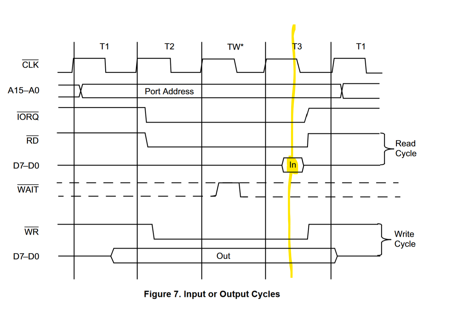
The highlighted bit is the window you have to make sure your data is presented to the bus for the I/O read to pick it up (the M3 cycle). It’s ok to be there earlier (as long as it’s whilst /IORQ and /RD are both low), but it’s bad if it’s afterwards.
So we have to make sure that we’re setting the pindirs to OUT, presenting our data to the bus via pins, holding them for just long enough and then setting pindirs back to IN to make our Pico go passive again.
I found that the bes solution to this was to acknowledge that the TX FIFO is a 32-bit word, so it can encode more data than what we need to send. I made it encode the pindirs too.
So when I latch the keyboard value, I now clear any outbound TX values (to remove stale presses), and then push a value encoded as: 0xXX00DDFF where XX doesn’t matter, 00 is the value for pindirs when we’re turning them off, DD is the data we want to send and FF is the value of pindirs when we start the process.
This is turned into pioasm:
    pull noblock        ; format is xx00DDFF
    out pindirs, 8      ; should be FF to turn on data out
    out pins, 8     [31]; the actual data
    nop             [31]; keep pins set
    out pindirs, 8      ; should be 00 to turn off data out
I set my state machine to use the “sticky” setting by calling sm_config_set_out_special. This allowed the nop to keep the pins at the required level until I turn them off. I suppose I could set the pins before the pindirs, but I don’t know if it matters much as long as the data value is asserted during the Z80’s M3 cycle.
The next bit is the use of noblock on the pull; if the TX buffer is empty the PIO will use the value in scratch register X, which we know is 0x00000040. This will affect the pindirs, but will essentially send zero back to the bus and then turn the pins off again. Given we only hit this code when we are responding to the correct port, it’s not an issue.
The timings here are much better; I could probably shorten that window significantly but it seems to be good enough for now.
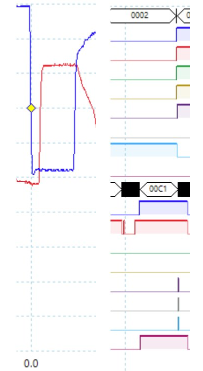
And hooked up, the Z80 saw the data I was sending (hardcoded to A for testing).
So here’s the PIO code in full:
; Listens to /IORD active low
; reads pins, matches port, replies with data
; pins mapped
;   IN  A7-0
;   OUT D7-D0
; IORQ pin is GP26 (23)
.program system_bus_iord
    pull block          ; pull the io port from TX
    mov X, osr          ; fill X with the port
    wait 1 gpio 26      ; wait for /IORD high (system boot)

.wrap_target
    wait 0 gpio 26      ; stall until the /IORD is LOW
    in pins, 8
    mov Y, isr          ; read pins into Y
    push noblock        ; I don't know why but it needs this
                        ; Y contains a different value without it? ($44)

    jmp X!=Y, next      ; if it doesn't match our port, done

    pull noblock        ; format is xx00DDFF
    out pindirs, 8      ; should be FF to turn on data out
    out pins, 8     [31]; the actual data
    nop             [31]; keep pins set
    out pindirs, 8      ; should be 00 to turn off data out

next:
    wait 1 gpio 26   ; wait for the /IORD to go high
.wrap
The remaining bit is to set pins A0-A7 as input pins, and D0-D7 as output pins, but set their direction to input.
You will notice a comment about the push noblock; that’s worth discussing. I found that for some reason, the contents of Y would have the wrong pins set which meant that my jmp would always succeed. I proved this by writing the values of X and Y to pins and saw that Y (which came from pins A7-A0) had bit 2 set. I set about debugging this by pushing the data to the RX FIFO and dumping it to my screen (having the composite out for this was VERY handy). I found that the values of X and Y were IDENTICAL. No variance, not even a single bit. I was stumped for a few hours on this; and eventually backtracked to a point where with the push the thing would work and without it, it wouldn’t port match. It was as if the value in Y wasn’t set properly until the push. I dunno if this is a timing thing, or some bug in the RP2040 itself, but it stumped me almost to the point of giving up. I probably wouldn’t have figured it out if it wasn’t for being able to display the value on the screen. I may spend a little more time to see if I can figure out exactly what it is, but for now - it works.
The ultimate test
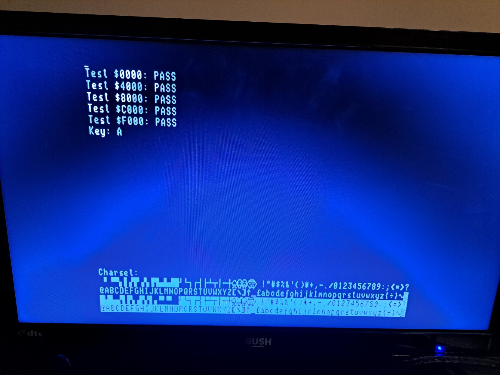
The final test is whether I can type in realtime and have the Z80 pick up the right keys…
To quote Adrian from Adrain’s Digital Basement, “It’s freaking working!”.
The key shown is a debug thing on the Pico itself (it’s writing directly to screen ram), the part that says Key: X is the Z80 seeing the key and writing to its own screen. They’re perfectly in sync and it’s responding really nicely. I was so happy when this finally worked :)
Mop up
The bits I need to do in order to finish this keyboard up is the boring stuff; deal with modifiers and make sure the keys are mapped to the right ones for the Interak. I’d also like to look at a special Pico-only menu which lets me toggle between 32, 64 and 80 columns. That would give some decent utility to the device.
The next steps in this project is to hook up the /IOWR to allow me to enable the Interak’s programmable graphics characters; maybe I’ll also think about implementing the hardware cursor the VDU-3 based machines have, although that probably means emulating the 6845 CRTC in the pico. Hmm, there’s an idea…
Anyway, I hope that was useful to you.