ZX-Sprite
This is a short series about exploring ZX-Sprite, a fantasy hardware add-on for the ZX Spectrum that aims to bring Spectrum Next style sprites to the 48K and 128K systems.
The series
- ZX-Sprite Introduction
- ZX-Sprite Prototype - Address decoding (this post)
- ZX-Sprite Prototype - Baremetal Pi GPIO
Introduction
The last post introduced the idea of ZX-Sprite, a port of the Spectrum Next’s sprite system to the ZX Spectrum hardware.
This time around I’ll talk about my initial attempts to build a real version of the system, starting from the very basics.
To create a real ZX-Sprite interface we must support:
- display of the ULA screen
- overlay of the Next-style sprites
- ULAplus for extended palette support
Without the ULA screen, you are basically controlling a second display of only sprites. Whilst cool, it’s not exactly useful. So part of the challenge here was going to be the question of “how do I capture the Spectrum’s screen?”.
HDMI via Raspberry Pi
I spent a couple of evenings reading about how others tackled the problem of capturing the ULA screen. I came across four solutions to the problem:
Of those 4 solutions, 2 of them use a CPLD with Raspberry Pi Zero to output to HDMI, and the others use another microcontroller with glue logic to output a VGA signal.
I figured that I’d start with the Raspberry Pi variant, mostly because it output HDMI which was easier for me to work with on my TV (I’ve had issues with VGA output in the past).
The Raspberry Pi Zero also has 27 GPIO ports that gives a few additional signal lines that would be needed for the full ULAplus and ZX-Sprite combo.
ZX Spectrum IO
Now that the ‘videocard’, the very first thing I wanted to do was to learn how hardware interfaces to the ZX Spectrum work.
Here were the rough order I decided to tackle this in:
- blinking an LED from the Spectrum
- flashing a Raspberry Pi’s onboard LED from the Spectrum
- changing the Raspberry Pi’s framebuffer colour to that of the Spectrum border
- moving a pre-defined sprite on the Raspberry Pi’s screen via the Spectrum
- displaying the Spectrum’s screen on the Raspberry Pi
- a demo of multiple sprites overlayed on the Raspberry Pi screen
So the first challenge was set; I needed a “hello world” of a blinkenlight that is controlled by the Spectrum.
For that, I’d need a way of connecting to the Spectrum’s expansion bus! Luckily, ByteDelight sell a Speccy Breadboard. This device exposes all of the edge connector lines as two rows of header pins connected to a tiny 40 row breadboard - perfect for prototyping!
Speccy blinken
The first challenge is to make the Sinclair BASIC command OUT (31), 1 light up an LED.
As this is an OUT command, we need to listen to writes to io port 31. This involves the following signals from the Speccy:
| Line | Description | Action State |
|---|---|---|
| IORQ | IQ Request signal; active low | LOW |
| WR | Write signal; active low | LOW |
| M1 | CPU ‘start instruction signal’; active low | HIGH |
| A7-A0 | Value: 31 | Pattern 0001 1111 |
When IORQ and WR are LOW we’re performing an IO WRITE. M1 must be HIGH to handle the
maskable interrupt acknowledge case.
After that we need to decode the address lines; for this we can refer back to part of the circuit from the Kempston Joystick Interface.
The Kempston interface decodes port 31 by monitoring address lines A5, A6 and A7. When all are LOW the Kempston Interface activates; this means that the real 8-bit port we’re monitoring is specified as 000x xxxx. This is called partial decoding and was relatively common back in the day, mostly because it meant you could get away with using a single 3-8 line decoder IC and there were relatively few peripherals on the market.
So I desoldered the 74LS138 3-to-8 line decoder IC from the Kempston interface I stripped down and stuck it on a breadboard.
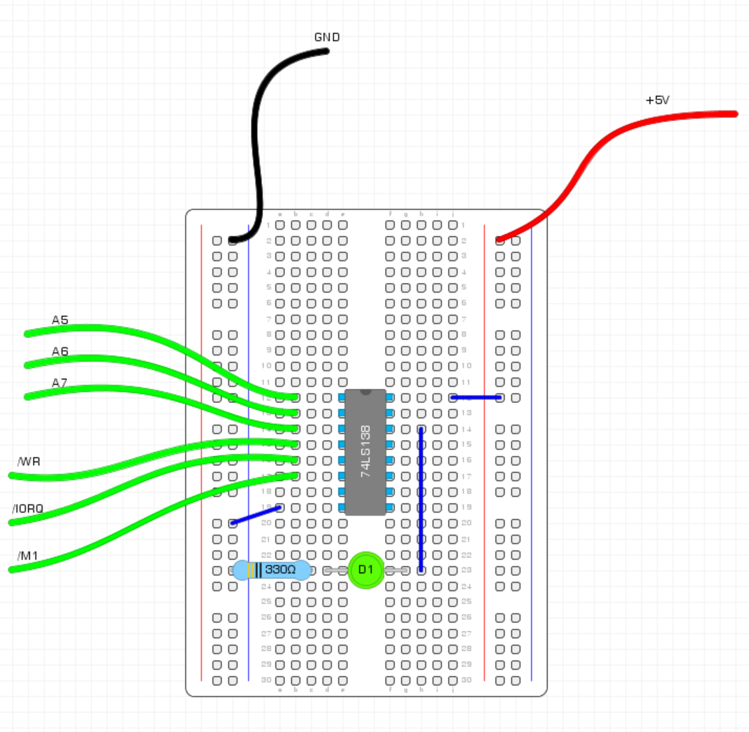
Running this I found that the light did turn on, but it was very quick. What we needed to do is latch the state of the LED so that it retains the last value.
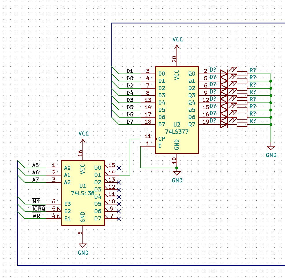
To do this I used a 74LS377 octal buffer that I had lying around. This has 8 inputs and will latch the values when clocked; so I tied the clock to the output of the `138 we used to decode the address.
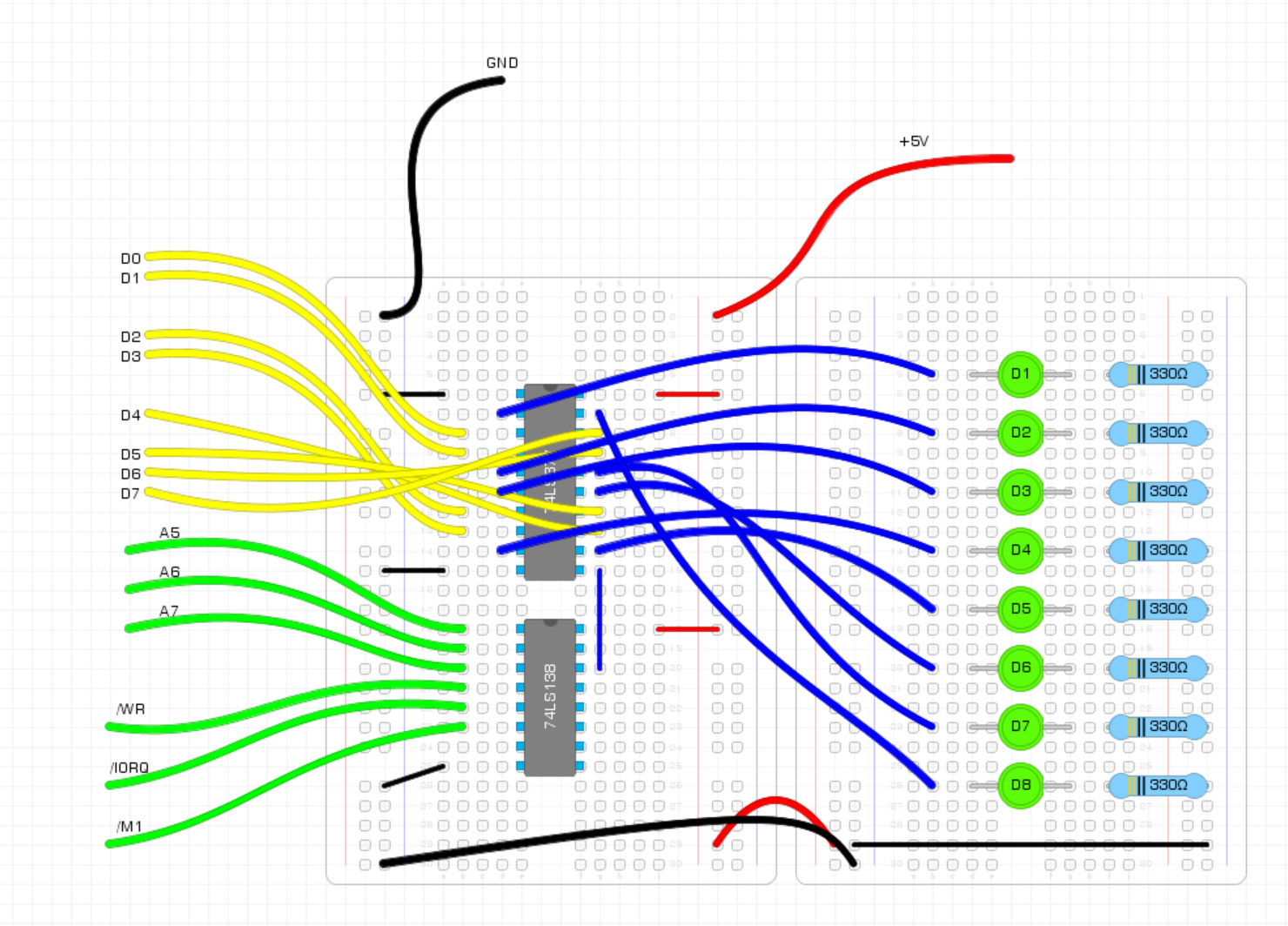
With the latch set up I could start sending data to the LEDs; I just needed to hook the various data bits up the Speccy breadboard.
As you can see on the diagram, the wires mount up FAST. So I’ll start using electrical schematics from herein.
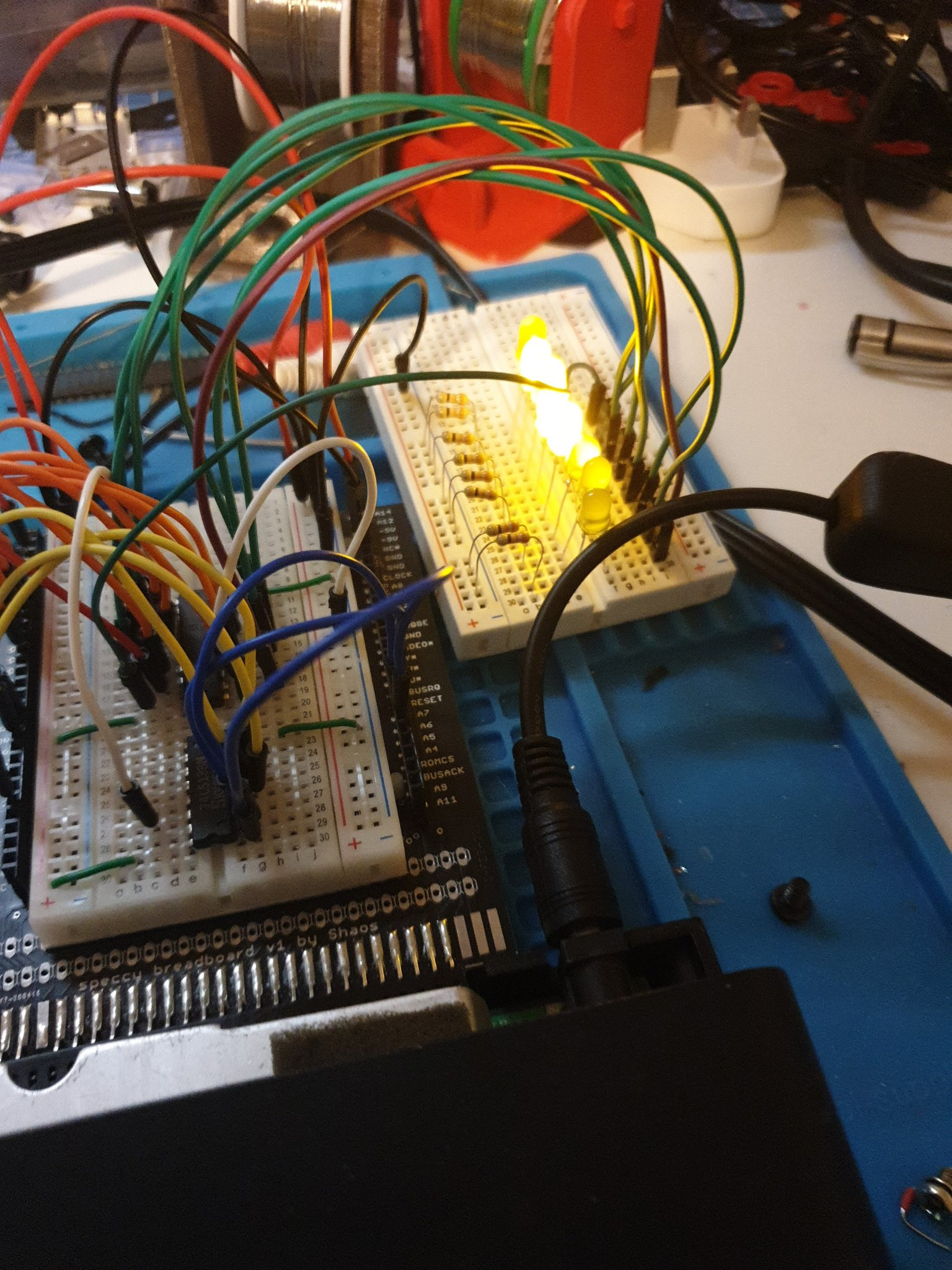
And with that I could send any value on to my port and have it show up in binary on the LEDs.
Decoding multiple ports
This is great, but what we really need to do is decode several ports.
For ZX-Sprite the minimum requirement would be the $303B SELECT $xx57 ATTR and $xx5B PATT; but the reality is that we’d need the ULA port and the various ports associated with ULAplus as well!
But let’s start small and focus on the 3 ZX-Sprite ports. The first thing that stands out is that one of the ports is a full 16-bit port - we can no longer get away with the partial decode hack!
I mulled over how to handle this; the final solution was likely to be a CPLD like ZX-HD/ TK-Pie use, but I decided to learn how GALs work. It’s something I’ve always been fascinated in using, especially as they’re one of the earlier forms of programmable logic devices.
After speaking to @BreakIntoProg on twitter, he kindly pointed me towards the GAL22v10 range of chips. It’s something he’s used in his computer-on-a-breadboard project, so I knew it’d be decent route to take.
GALs are a form of programmable logic device (PLD); what that means in practice is that we can program them to execute combinational logic for us. The GAL22v10 range has 22 user pins (+ 2 power), of which 10 can be configured as outputs. They can be programmed by an EPROM programmer and the code can be written in a simple definition language called GALasm.
I went through a few iterations on how to best use the GALs for handling multiple addresses; I ended up with a solution that took in the 3 control signals (IORQ, WR, M1) and the 16 address lines, it then provided 3 outputs - an active low CTL signal and 2 control data line (CT0 and CT1).
                                GAL22V10

                          -------\___/-------
                      IRQ |  1           24 | VCC
                          |                 |
                       WR |  2           23 | CT1
                          |                 |
                       M1 |  3           22 | CT0
                          |                 |
                       A0 |  4           21 | CTL
                          |                 |
                       A1 |  5           20 | A15
                          |                 |
                       A2 |  6           19 | A14
                          |                 |
                       A3 |  7           18 | A13
                          |                 |
                       A4 |  8           17 | A12
                          |                 |
                       A5 |  9           16 | A11
                          |                 |
                       A6 | 10           15 | A10
                          |                 |
                       A7 | 11           14 | A9
                          |                 |
                      GND | 12           13 | A8
                          -------------------
I ended up on this solution as the 2 data lines allowed me to decode 4 IO ports and signal them in the 2 bit value. Other solutions I tried was to emit the 3 ZX-Sprite signals as discreet signals (SELECT, ATTR & PATT), which worked fine until I needed the ULA border as well.
The decoding looks something like this:
Addr  | Mask                | CTL | CT0 | CT1 | Notes
---   | ---                 | --- | --- | --- | ---
$303B | 0011 0000 0011 1011 | L   | H   | H   | SLOT
$xx57 | xxxx xxxx 0101 0111 | L   | H   | L   | ATTR
$xx5B | xxxx xxxx 0101 1011 | L   | L   | H   | PATT
Whenever our CTL signal goes low we’ve decoded a port; the exact port we decoded is shown on the CT0 and CT1 lines.
GALasm is nice and logical (pun intended). It has assignment of the output ports and then uses logic operations AND (*), OR (+) and NOT (/) to derive a value.
A simple example of an NAND gate would be:
/Q = A * B
Essentially, assign A AND B to the output Q and invert it.
The GALasm code was surprisingly simple for the 3 port decoding I needed to to. The main ‘bulk’ of it is the sheer number of address lines, that and the IO WRITE detection.
IRQ WR  M1  A0  A1  A2  A3  A4  A5  A6  A7      GND
A8  A9  A10 A11 A12 A13 A14 A15 CTL CT0 CT1     VCC

CT0    = M1 * /WR * /IRQ * /A15 * /A14 * A13 * A12 * /A11 * /A10 * /A9 * /A8 * /A7 * /A6 * A5 * A4 * A3 * /A2 * A1 * A0 ; 0011 0000 0011 1011 (SLOT)

CT1    = M1 * /WR * /IRQ * /A7 * A6 * /A5 * A4 * /A3 * A2 * A1 * A0 ; xxxx xxxx 0101 0111 (ATTR)
       ;+ M1 * /WR * /IRQ * /A7 * A6 * /A5 * A4 * A3 * /A2 * A1 * A0 ; xxxx xxxx 0101 1011 (PATT)

/CTL    = CT0 + CT1  ; Control is active if any of the two data signals are high
I originally tested the GAL itself on a breadboard, manually setting the inputs to HIGH/LOW logic states and using 3 LEDs to observe the resulting output. It worked first time!
After knowing the GAL was sound, I removed the 74LS138 from the breadboard, replaced it with a programmed GAL22v10 and wired the additional address lines in. The CTL line was connected up to the latch clock and presto, I could issue OUT commands on ports 12347 ($303B), 87 ($xx57) and 91 ($xx5B) and see the data latched onto the LEDs as before.
Life of Pi
Confident that I could connect the Spectrum up to a circuit and start handling the IO requests, I then turned my attention to the Raspberry Pi. I needed to interface to the Pi to “do stuff” - but what does that mean?
I’ll cover my first tentative steps into Raspberry Pi Baremetal in my next part of this post.