In my last post I talked about the original Interak and the “new school” variants from the current enthusiast community. This time around I’m going off on a slight tangent, athough it’s adjacent to the subject matter so I hope you’ll forgive me.
For a while now, I’ve been thinking how to create a display for a breadboard computer. There’s three approaches out there:
- Memory mapped
- I/O based display
- Serial terminal
Memory Mapped Displays
The memory used by the video output is shared by the main system; these types of displays were very common in the early microcomputers of the 1980’s. The ZX Spectrum, Interak, Amstrad CPC and BBC Micro all used this style of display - there was some RAM that the CPU could read/write, and that same RAM was used by the video drivers to create the display.
These sorts of displays are intuitive to work with from a programmer’s point of view; you “simply” write data to the memory and it shows up. One of the challenges from the electronics point of view comes down to dealing with the problem of bus mastery; only one component in the system can access this display memory at one time. This was worked around in various ways; such as wait states (to halt the CPU), or very clever timing synchronisation tricks to ensure that the CPU wasn’t using the memory at the same time as the video driver.
The other trade off here came at the expense of the video memory occupying system memory, which then became “lost” to the system itself. Different systems such as the ZX Spectrum came up with novel ways of decreasing the amount of memory needed by encoding the display in a specific way.
I/O based Systems
These sort of systems dealt with the bus mastery problem by isolating the video memory from the rest of the system. The CPU couldn’t access this directly, instead it had to go via a dedicated video driver chip such as the TMS9918 used in systems such as the MSX and Sega Master System (although the Master System used a customised version).
Writing to video memory would involve a series of I/O requests to set up the address, and then a range of I/O requests to pass data to/from the video memory. A huge benefit of this is that the system gets to keep all of the memory; a 64K system is a true 64K system with all that RAM available to the CPU.
These displays are command-based, in that you typically use registers to issue commands to the chip. One such command would be “set the write address”, and the next would be the address data that follows it. As a result it takes a little more setup to deal with the display, but many of the commands are designed for bursts of contiguous data.
Another big benefit is that you can use fewer pins to address the display itself. Typically you’d use 8 address pins for the I/O port, 8 data pins and then IORQ and RD/WR signals. The TMS9918 went even further and exposed only data registers and a chip select to the system, requiring something like a peripheral parallel interface (PPI) to sit between the CPU and the chip to deal with the I/O addressing.
Serial terminals
A
serial terminal can expose a system interface from a single TX pin. Ok, that statement is oversimplfying the problem somewhat, as it’s bypassing the serial IO driver or UART. And that’s one of the things here; the serial terminal requires a dedicated serial chip/card on the computer to drive it.
It’s worth noting that one huge benefit of serial terminals is that they are great for interfacing with breadboard computers, usually because the owner needs a way of getting data in and out of the system, so will likely need the serial for that. Indeed, many people will use their laptop and a terminal emulator such as PuTTy as the “display” for their breadboard (the RC2014 is a good example of this).
Although typically used to output text, serial terminals are also command-based; they accept a series of control codes to do certain things, such as move the cursor, change the character colour and so on. There’s a variety of standards for these control codes and what they do. Typically these codes are embedded in the data stream itself and need to be parsed by the terminal to perform the action.
The RC2014’s picoterm is one such example of an ANSI-terminal based display; another is the Agon Light which uses a custom protocol to drive an ESP32 graphical display over a serial link.
The Interak VDU
The Interak had 2 types of VDU; a serial based display and a memory mapped display. I believe that most home users would have used the memory mapped card, so that’s what I’ll cover here.
The Interak’s VDU and VDU-2K are simple, monochrome character-based displays that are memory-mapped into the CPU’s address space. They contained an internal character ROM that contained the pixel graphics for the font and this was used output characters to the screen. If you wrote an ASCII ‘A’ to the address$F000 (top left), the screen would output a letter ‘A’ in the top left. Any character with the high bit set (aka >=128) would display the character with inverted colours. They had no pixel manipulation, hardware scrolling, cursors, or any of that business - it was straight character output!
The VDU could be configured to display in either 32 or 64 character modes, and you would have to deal with that in software by writing to the correct addresses. For example, writing to $F020 in 32 column mode would output at the first character on the second row. However in 64 column mode, it would write to the 33rd character of the first row (assuming zero-indexing). This meant that any software written for one mode would display incorrectly in the other.
A “programmable” graphics card was available which allowed for the user to specify their own character graphics. This worked by providing a separate, specific RAM area for the user to write their character data to and then enabling the character set via an I/O request. Electronically it worked by mapping in the user’s RAM instead of the character ROM for pixel output.
The Project
All of this got me thinking; could I create an Interak-style VDU for mt breadboard computer? If so, how would I do it?
I wanted:
- Composite or VGA output (monochrome is fine, maybe even ideal)
- Memory-mapped VRAM
- Character-based output of 32 and 64 columns (80 would be a bonus) by 24 rows
- Ideally support programmable character sets
- Ideally have an I/O interface for enabling the programmable characters
I did a lot of digging into Ben Eater’s TTL VGA card, George Foot’s play on it and more. Ultimately I ended up bumping up against the problems of memory mapped video cards, dealing with bus synchronisation timings and so on.
The work I did on the ZX-Sprite prototype a couple of years back taught me that I can passively “bus sniff” memory writes to the ZX Spectrum’s screen memory and build my own framebuffer from them. The analysis I did on the Interak VDU-3 in my last post made me realise that they’re employing the same technique; the card is a passive (write only) participant in the bus (at least where the screen memory is concerned).
So I started thinking; can I watch screen memory writes, capture them and output a screen from the Raspberry Pi Pico?
I started this journey looking at the Pico-mposite project by Dean Belfield. This project is pretty intriguing; he’s driving a greyscale (or colour) composite TV display from the pico and addressing it via a serial link.
Then I looked at the Pico’s VGA demo board to look at how I could use such a system. This provided an interesting (albeit highly confusing) example of VGA output and left the rest up to the user.
So yes, it’s perfectly feasible to drive either a VGA or composite display from a Pico. A past experiment I did demonstrated that it’s possible to drive a monochrome PAL signal from an STM32 using 2 signal lines. I decided then that my screen driver code would be based upon Dean’s excellent work on the Pico-mposite, but it would need reworking to a) support my character based system and b) use a 2 signal line monochrome display.
The next part is to figure out what I’d need to do to connect this up to the system bus. A cursory glance would mean we need 16 address lines, 8 data lines, /MREQ and /WR. That’s 26 GPIOs for the system bus and 2 signal lines for the display; which is more GPIO we have to play with on the PICO.
The Interak’s screen memory is mapped from $F000 to $F7FF, and the programmable graphics from $F800 to $FFFF. This is convenient, as it means the upper 4 bits of the address are always high. I would take an 74LS08 quad AND gate and feed A15 & A14 into one gate, A13 and A12 into another and then feed the outputs of those into one of the remaining gates, this would yield a HIGH signal if the address matches $Fxxx and LOW if it does not.
This signal can be used with /MREQ and /WR to drive an 74LS138 3-1 line decoder to emit a single /VRAM_WR signal.
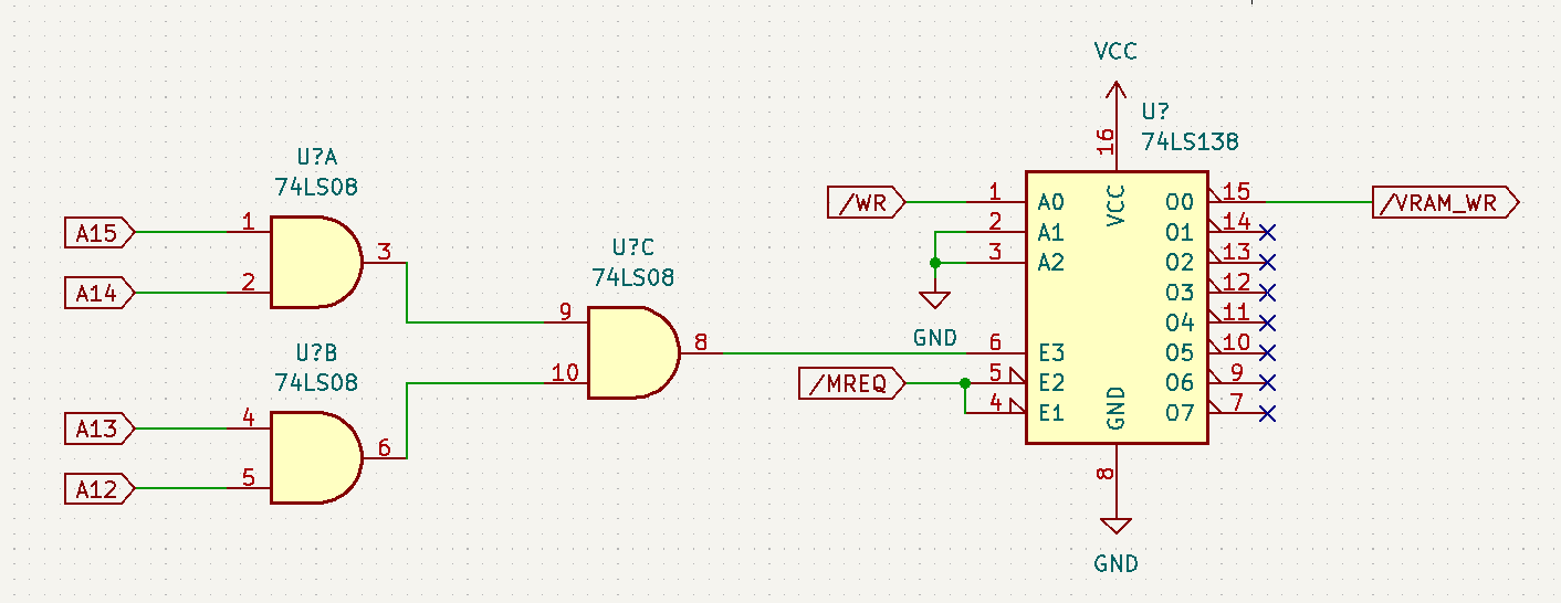
Combined, this allows us to turn 6 signal lines into 1, meaning we’re now at 23 GPIO, which fits.
This post is getting a little long, so I’ll continue in the next part, where I’ll talk about how I went about interfacing this to the Pico.