This is the third post in a series about building an RC2014 compatible Z80-based machine from scratch. It’s based loosely around the Amstrad CPC 464.
In the last post I talked about designing the Z80 Cpu module and the backplane.
Clock Module
One of the things that a CPU needs to operate is a clock. It’s the thing that ticks through each cycle and makes the CPU does its thing.
Modern Z80 CPUs can be clocked much faster than the ones from the 1980’s. For example, the ones I have will happily run at 10Mhz. Some of the eZ80 CPUs can be clocked much higher than that.
I decided to run the CPU at 4Mhz to match that of the Amstrad 464; it’s also a better fit with breadboards and home made electronics which have more noise, longer traces and can suffer from “reflection” at higher signal rates.
Let’s take a look at the clock circuit that I designed for the original breadboard:
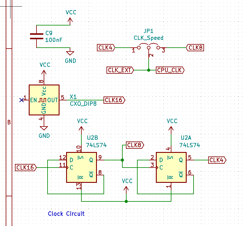
We start with a 16Mhz oscillator can. These things are pretty neat - you supply power and get a stable clock out of it. It’s much more compact than the usual crystal resonator circuit that needs a couple of caps & resistors.
Many people use a clock that’s dividable into a standard baud rate to make things like serial IO and TV out easier. The
RC2014 clock module uses a 7.3728MHz main clock, for example.
I won’t be doing this as I wanted to stick closer to the CPC clock times. This means that my serial IO circuit will need its own independent clock, but I’m fine with that. Unless of course I misunderstood something along the way. I guess I’ll find out down the road.
Dividing the clock
The 16MHz clock is used to clock a 74LS74 flip-flop which is configured in such a way as to feed the output into itself. This has the effect of dividing the 16MHz clock to an 8MHz clock. We do this twice to get down to 4MHz - this will be our system clock.
This particular method of dividing the clock is based on Dean Belfield’s BSX project and it worked well on the breadboard version of my Z80 computer.
The RC2014 clock module uses a 74LS393 binary counter to achieve the same result. The benefit of this approach is that you perform 8-way division using just this chip, whereas the 74LS74 flip-flop approach requires two chip.
In addition to this main clock I had a slower clock based on a 555 which was useful for testing and debugging. I don’t think I’ll be adding the 555 clock directly to this board, but I will add a pin for an external clock.
This 4MHz clock could be passed directly to the CLK line on the bus and it’d be used to clock the CPU. This was how I did it on the breadboard and it worked well.
In the Amstrad CPC it’s the Gate Array that takes the 16Mhz system clock generates a 1Mhz clock for the audio/CRTC and the 4Mhz clock for the CPU.
Looking forward into the future of this project I think it’d be prudent to further divide the 4MHz clock to 2Mhz and finally 1MHz and then allow the various clocks to be routed to the CLK or CLK2 lines using jumper configurations.
This would give the system access to a 16MHz, 8MHz, 4MHz, 2MHz and 1MHz clock as well as accepting an external clock signal. It gives a variety of options and should mean I don’t need to rework the clock circuit much.
The circuit
So in brief, the clock module must:
- Provide a header for a
CLK_EXTline - Take a 16Mhz input oscillator
- Expose a
CLKline with eitherCLK_EXT,CLK_16,CLK_8,CLK_4,CLK_2orCLK_1depending on a jumper setting - Expose a
CLK2line with eitherCLK_EXT,CLK_16,CLK_8,CLK_4,CLK_2orCLK_1depending on a jumper setting
It may also be desirable to break out the different clock signals as their own headers should I need one of the other divisions down the line.
Using two 74LS74 and a 16MHz oscillator gives everything we need. I could also go with the 74LS393 solution, it’s simpler and should work just as well. It’s really a coin-toss which way to go; but I’ll start with the 74LS74 version as I already have the chips.
I’m going to attempt a hand-made PCB for this (instead of stripboard). Here’s the circuit layout as a single-sided pcb design.
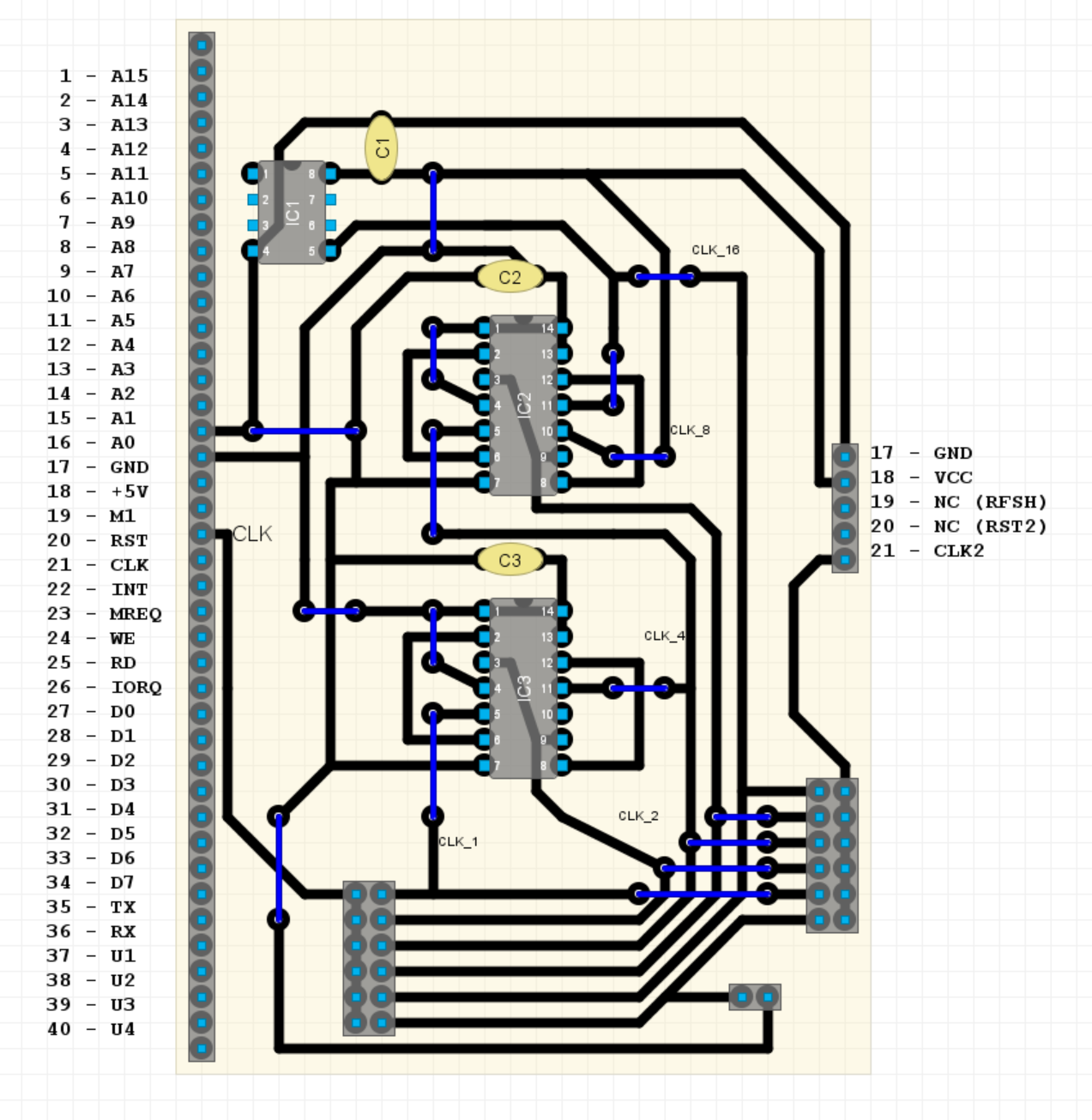
It was an interesting challenge trying to do this as a single-sided PCB (albeit with some mandatory jumpers). I’m really not sure how it’s going to work out trying to make this into a PCB by hand - I don’t expect much, especially from my first attempt, but you have to try these things - right?
I’ll document the process for the next post.
I just need to wait for the etching stuff to show up.
ret