Building a ZX Spectrum Lower Ram Replacement Board - Part 2
In my last post I talked about the broadboard prototypes of my attempt to build a Lower RAM replacement for the ZX Spectrum.
It was encouraging to see that something could work on a breadboard, even if it was glitchy. The long wires and extra capacitance would cause a lot of noise for something that needed to be accessed as frequently as RAM. I felt like it would be a good “next step” to build something “real” and try and hook it into the Spectrum.
This time around I’ll focus on the attempts to make working version on veroboard. I’ve never worked with veroboard before, so there was a lot of new things for me to pick up - but this is why I am doing what I am doing, to learn!
The layout
As I was going to be soldering this time round, I figured it was best to plan a layout.
I started by using KiCad to plan my board. I have never done veroboard layouts before, so this was new.
One thing I figured out very quickly is that trying to do veroboard layout in KiCad is a pain.
Veroboard is basically a pre-drilled PCB with strips of copper that join traces along a “row” - so in that regard it’s a little like breadboard. The main difference is that the traces run the length of the board, meaning you have to cut them to break them.
One can think of veroboard as being like a double sided PCB. The main traces are on the underside, and if you need to bridge over traces you need to use wire jumpers.
So typically, you’d have the “rows” as the underside, and then vertical jumper wires between these rows.
Board 1
For my first layout, I sat down and used KiCad. I will admit that it took a while and wasn’t fun.
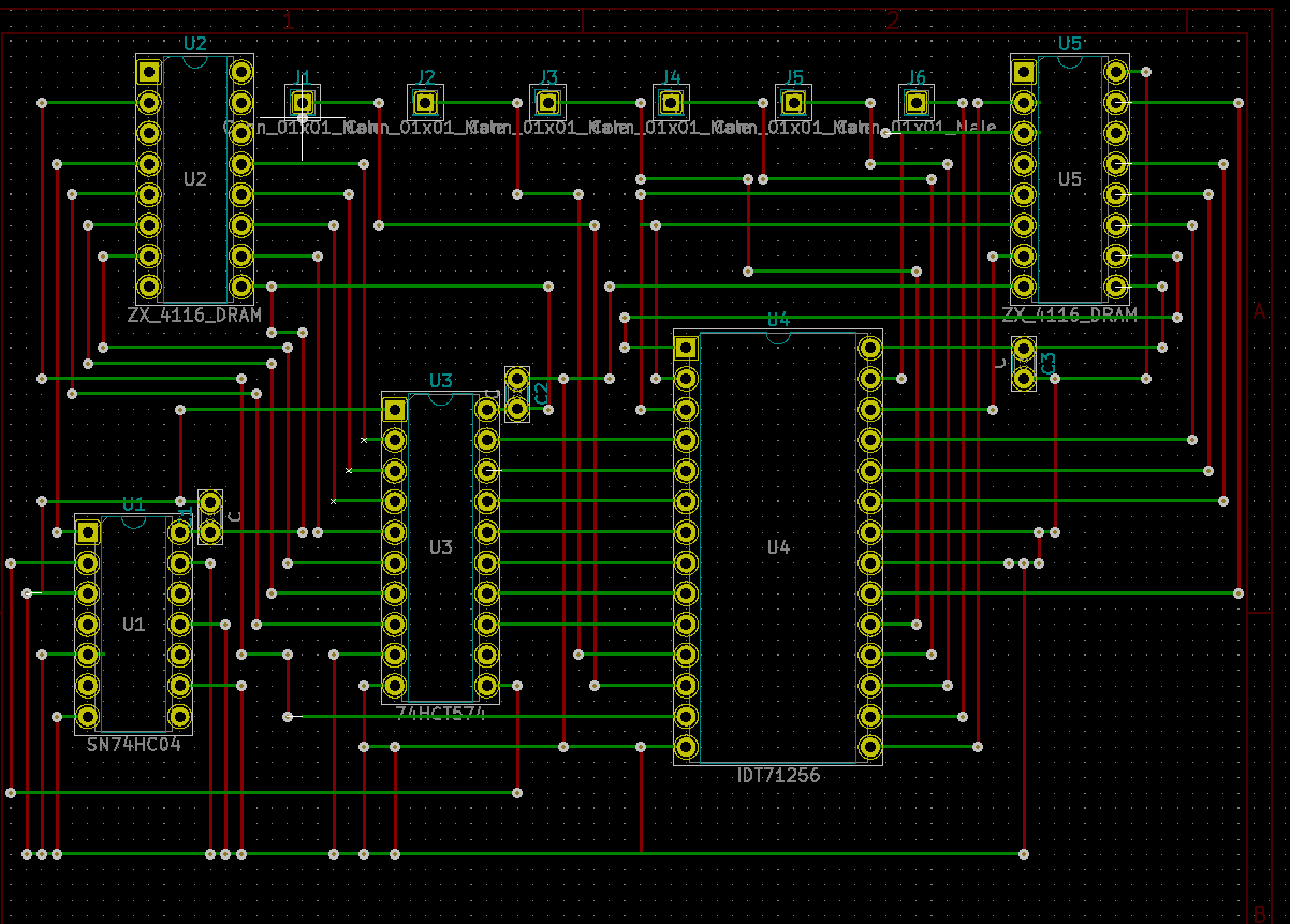
One thing I noticed straight away here was that there were more vertical jumpers than horizontal. Which was a bit of a sign I’d maybe got the orientation wrong, or that the wiring itself was going to be horrible.
When it came to build this board I… ran out of space. It took a while to figure out how, but it boiled down to the wire spacing in KiCad not being aligned to the through holes, basically I could pack in more traces in a space than I should have.
I don’t have pictures of the board as I ended up stripping it down for parts.
Board 2
I started in KiCad again but I found KiCad kept switching trace widths and it was far too easy to make a mistake and end up repeating the same error as last time.
So I went analogue. Graph paper, pencil, ruler.
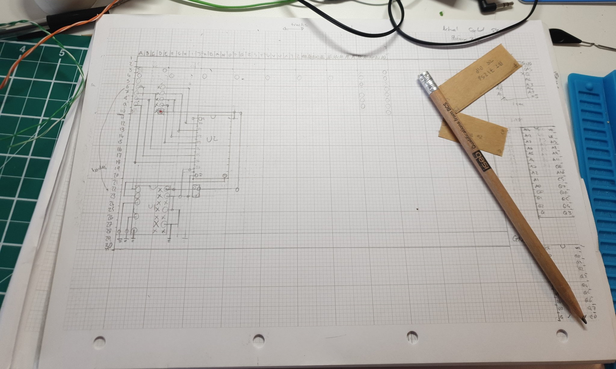
Doing it this way was quite satisfying and a lot of the pin layouts cemented themselves in my mind.
Up to this point I was using bare wire for the vertical jumpers - these were actually old capacitor legs that I bent. However I ran out and only had thin wire I’d salvaged from a CAT-5 cable. I think moving to flexible wire started a bit of a cascading “downfall” of this build, in that my ‘veroboard’ wire discipline started to slip - I started taking shortcuts!
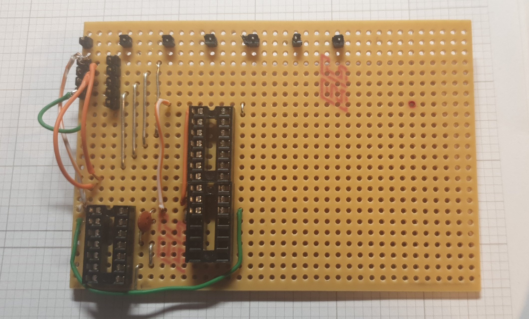
I made some “stencils” of the ICs and used them to help positioning - but this lead to the downfall of this design. I got one the wrong size, which meant I ran out of space and had to use a couple of bodge wires.
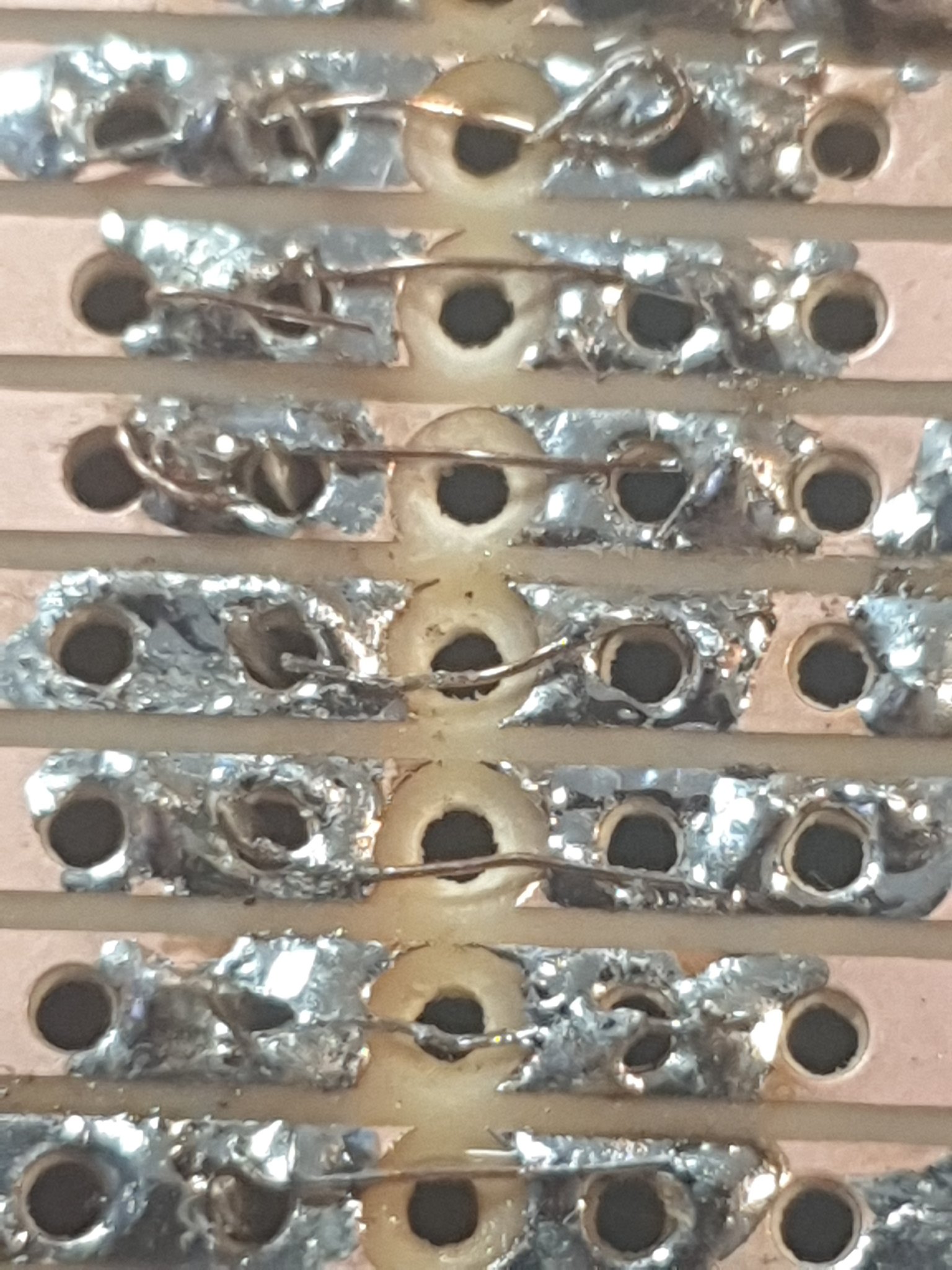
There were several errors in this board, from drafting errors to places where I cut the wrong track. I had to do some bodge repairs on these tracks.
This was the first time I came to making the “legs” for the socket on the board. I had the idea to use header pins, but for some reason I tried to solder wires to the top of them, which melted the plastic. Rework and other things also contributed to the plastic melting, and in all they ended up a mess.
With all that done, I “finished” the board and fitted to a spectrum.
I don’t have pictures, but it didn’t work. ULA kicked in, but I was presented with a black screen with various errors on it.
I didn’t have a scope at this point, so diagnosing these errors was hard. I would suspect that a combination of the broken traces, probably a short, or bad contacts to the main board was the root cause.
Board 2 is now gathering dust in a box, as I prepared to move to board 3.
Board 3
Board 3 I took the complete opposite approach. I decided to go 100% underboard wiring and just off-the-cuff it.
This board was a complete disaster.
I grabbed the leftover board from the aborted v1 attempt and just went at it.
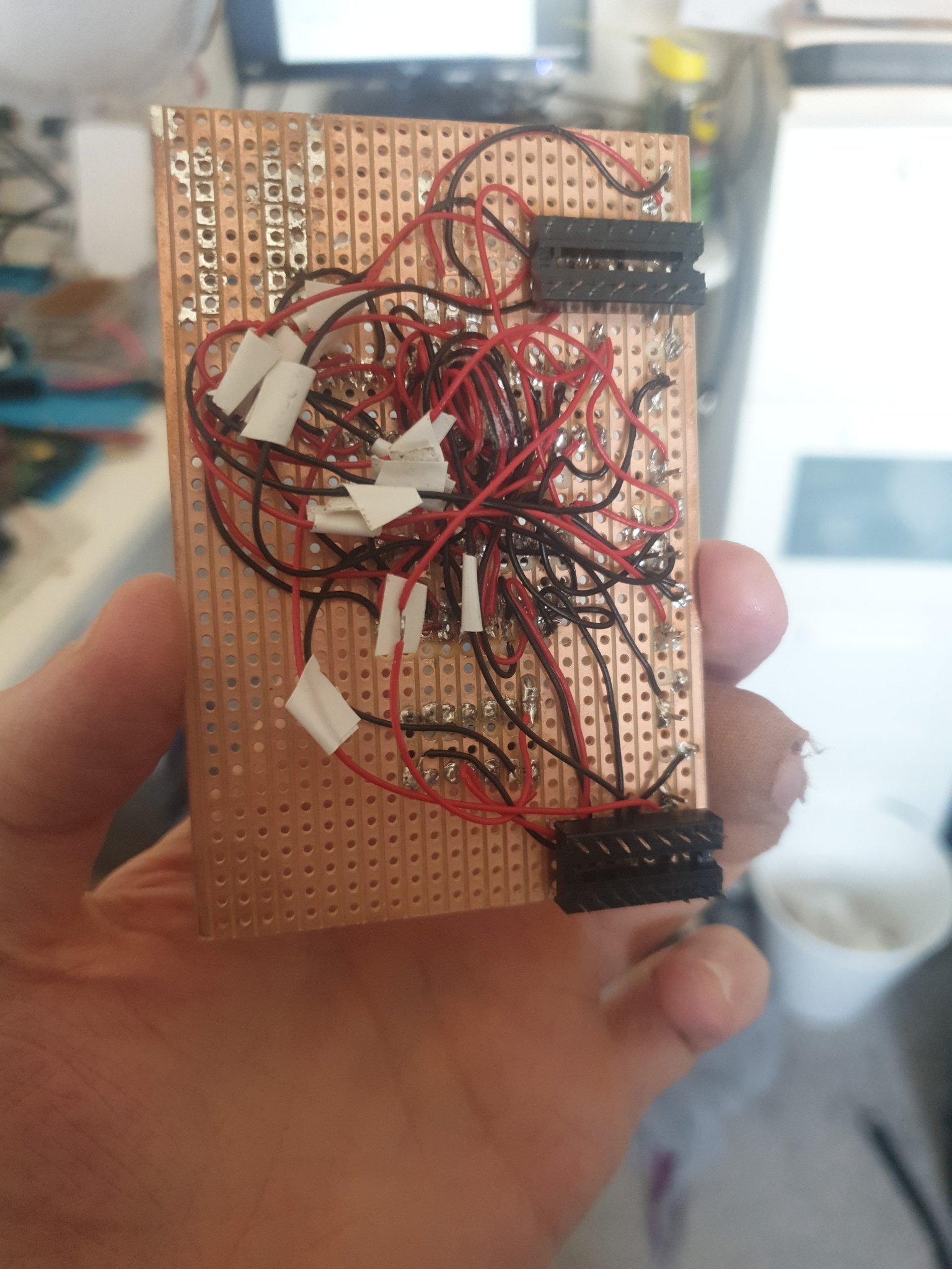
I used very short, thin wires that were hard to solder and tended to melt when the iron got near them. Even though thy were short, they mounted up quickly under the board - perhaps because they were short!
It didn’t work; I couldn’t debug it well due to the tight packing of the wires (even with a scope at the point!). I just trashed it into the failure box.
Taking Stock
At this point, I’d built several iterations of this board and had exactly one partially working version - the original breadboard build.
I took stock of the situation and what I’d learned so far. Planning the vero layout took time and was fairly hard to debug or correct if you got it wrong. A “wing it” approach in v3 really did me no favours - and underboard wiring was not going to work, even with very short wires.
I went back to basics and built a breadboard version again, knowing what I know to date.
The last breadboard
Keeping the wires short as possible and going for a “Ben Eater” style ethos, I constructed the breadboard and wired it into the Spectrum exactly as I wanted the daughterboard to work.

It highlighted to me that there’s a lot of crossing wires, which could lead to all sorts of issues.
To my surprise the breadboard version booted the Spectrum first time. No issues from previous breadboard attempts. It was there and I first thought it was completely stable.
Unfortunately there was a glitch that danced around; actually seemed to get worse over time. It could be inductance, or some other artifact from the breadboard & wire lengths.
However, I knew that the basic design was there and any of the veroboard failures to date must be construction related.
Board 4
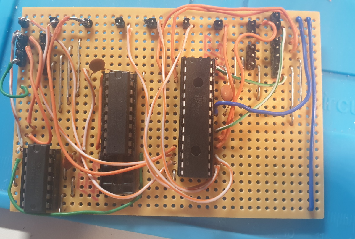
I decided to make a final(?) veroboard version based on the exact design here, borrowing the Ben Eater style wires.
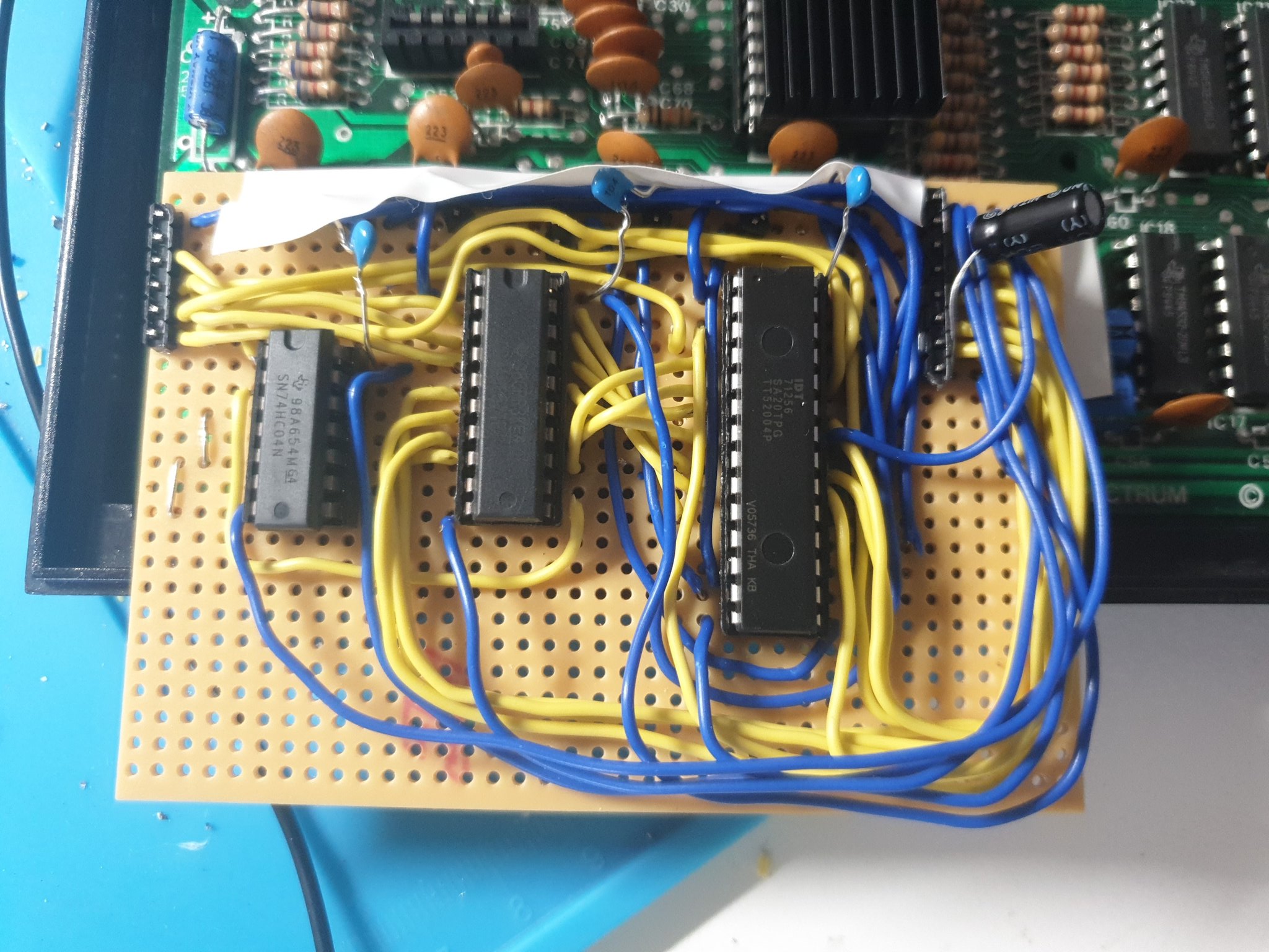
I used the “bus” style approach adopted from the breadboard, and bent the wires around in paths together. It was easier to build (although some parts got a bit tricky), and the decoupling caps stuck on at the end look a bit… odd.
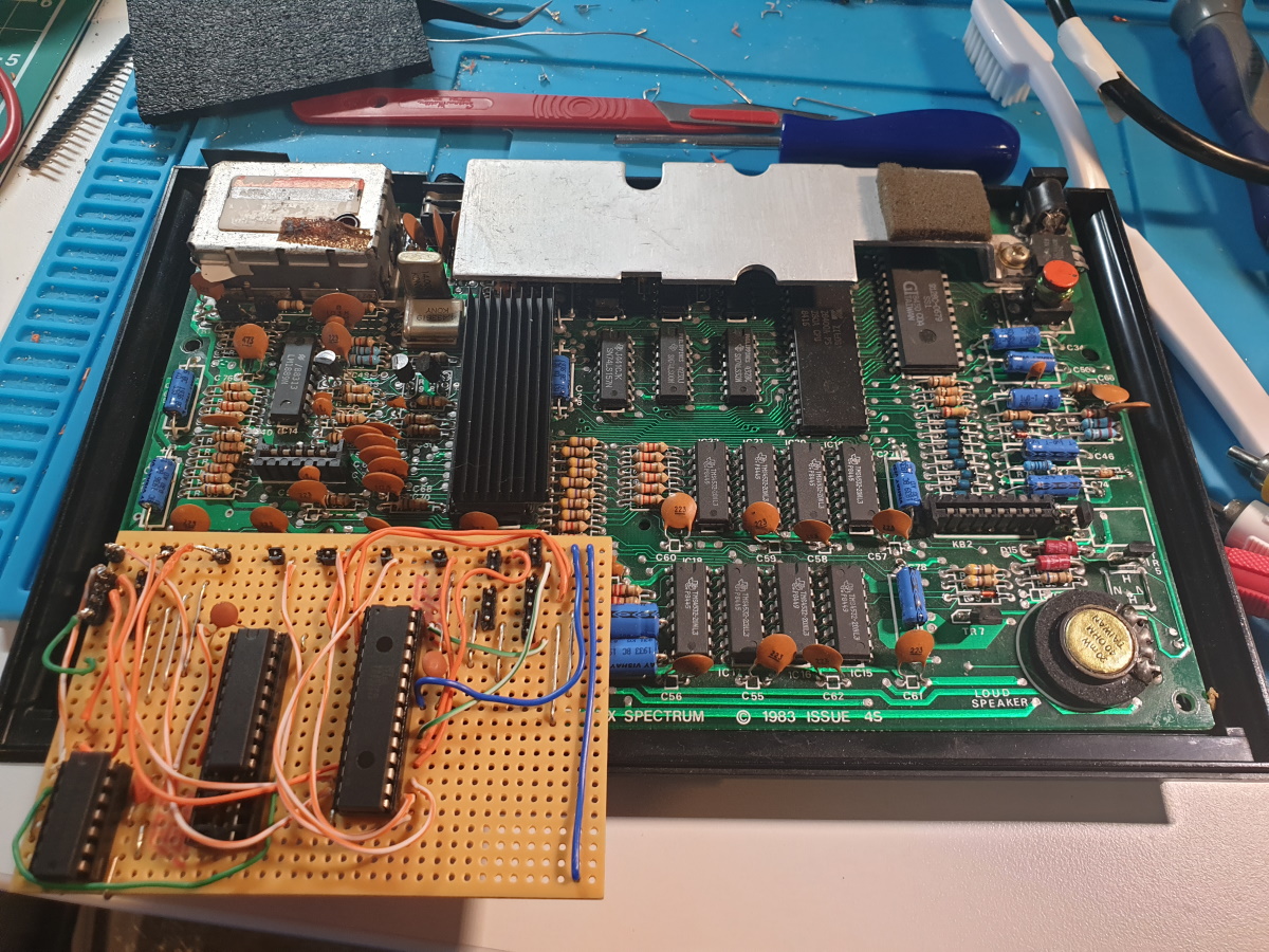
It also completely didn’t fit the case at all.
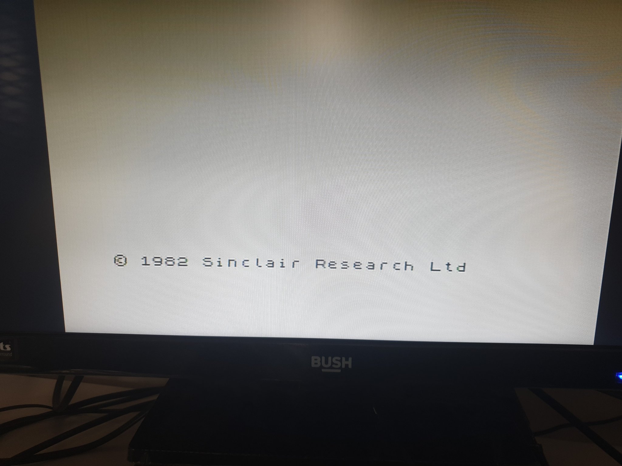
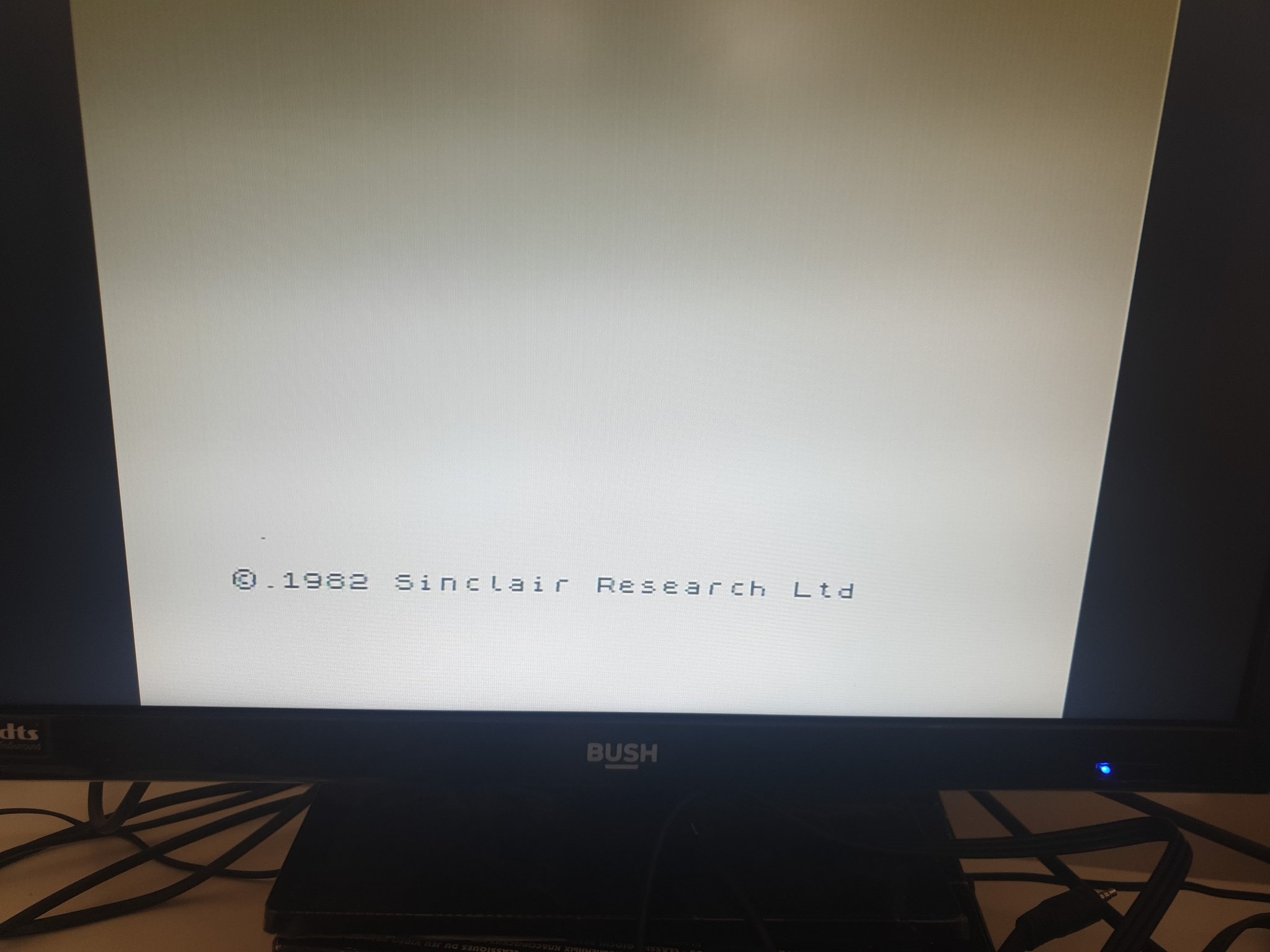
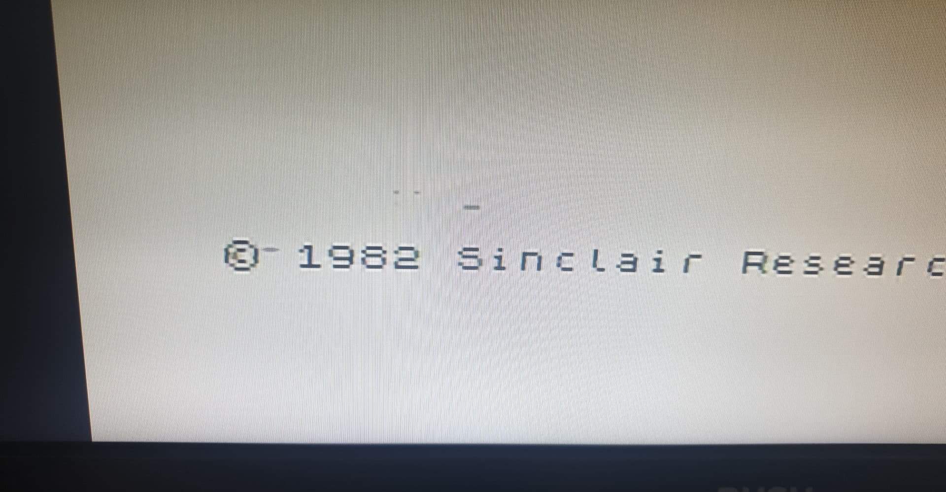
I want to pretend that it worked first time, but it didn’t. I had a couple of shorts and a mistake here and there, but in the end I got a copyright message.
And it was stable.
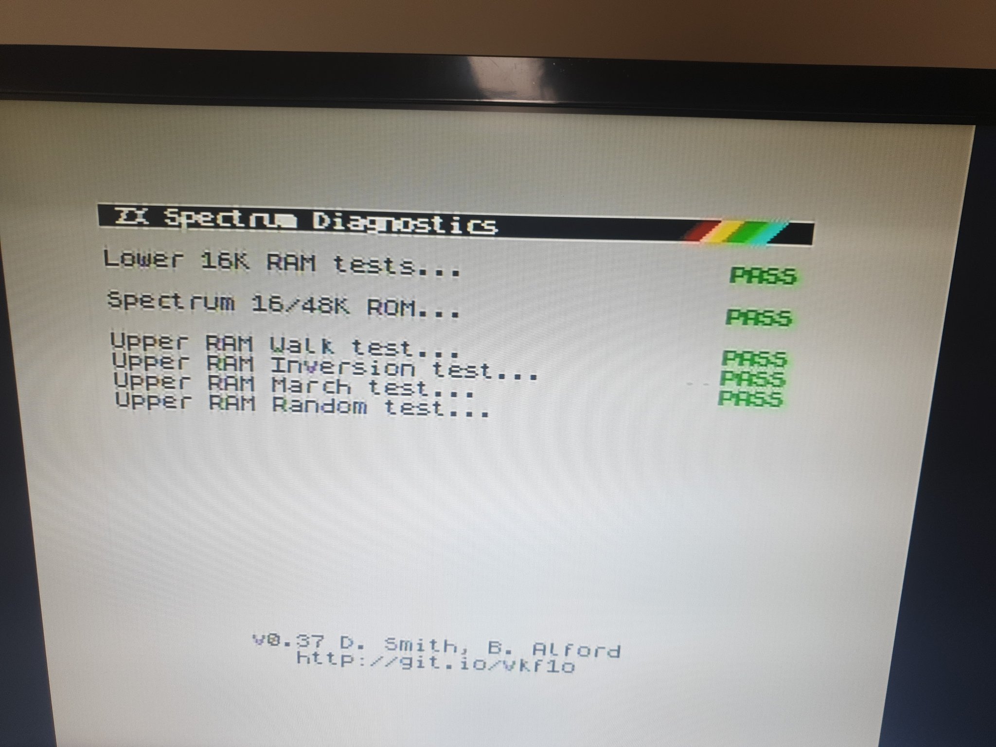
It passed the ByteDelight Diagrom test with no issues at all - I was elated!
Until I started to play a game - we had glitches.
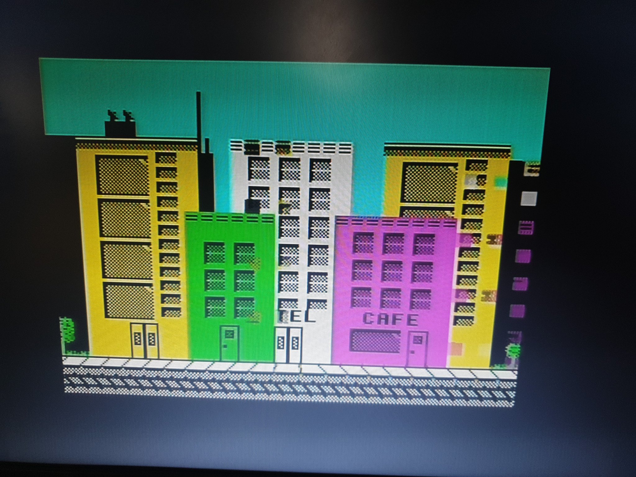
There’s no fault according to the Z80 - it passes the tests. There are no issues in program execution, to the computer the issue doesn’t exist.
Looking into this we can deduce that the fault must be on the screen read only, eg: the ULA reading large chunks of data out quickly with CAS strobes.
There’s a few potential causes to this.
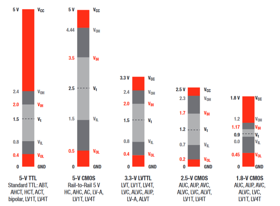
CMOS vs TTL
I used HC parts for the logic and register. These operate on CMOS voltages but with TTL-compatible outputs. The Spectrum is working on LS parts, so is operating at TTL voltage levels.
It is entirely possible here that the ULA doesn’t always trigger the CMOS inputs of the HC chips because the voltage is good enough for TTL, but too low for CMOS.
There is a thread that shows this.
This is something I was completely ignorant to when sourcing the parts for this build.
SRAM speed
The original 4116 DRAM used in the Spectrum operates at ~150ns to ~200ns access times. This is the time used to measure a CAS cycle, eg: the speed of read for a single bit, assuming the RAS is set up.
The SRAM I used here was 25ns, so was exceptionally fast compared to the original.
I have read in a few places that the Spectrum will work with as low as ~70ns access without these glitches. This is the speed of RAM used in the Harlequin clones, which are based entirely on SRAM.
I believe that this access speed may be an influencing factor on the graphics issues we see on this board.
Next steps
After half a dozen goes at this, I finally had something that worked, but it isn’t anywhere close to being usable.
It’s been a process of trial with lots and lots of errors, but a lot of learning has resulted from it too.
The next steps to try in this project are as follows:
- Swap out HC logic with LS/HCT logic chips
- Use slower 70ns SRAM
- Create a more compact layout, with the aim to fit the case
- PCB with SMD components
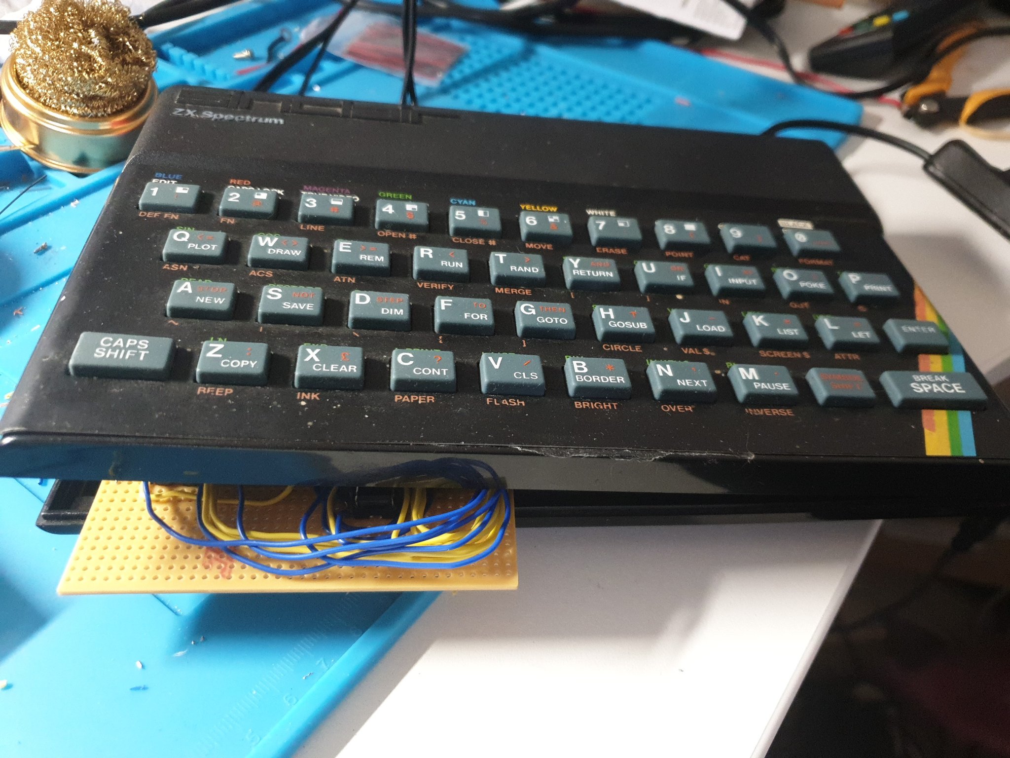
To wrap up, here’s a shot of the family.
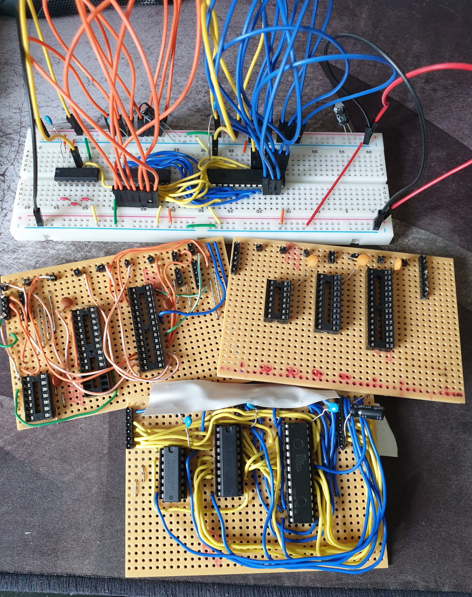
Until next time!