ZX81 Video Conditioning Mods
The ZX81 is notorious for outputting an RF signal that modern TVs struggle with.
This is a post that explores the video signal from the ZX81 and discusses a few of the mods for improving it.
ZX81 Composite Mods
Modern TVs have issues with the ZX81 RF signal, and most common solution is for people to modify their ZX81 for composite video out.
Knowing nothing about the subject, I rushed out and bought a kit from tfw8bit.com.
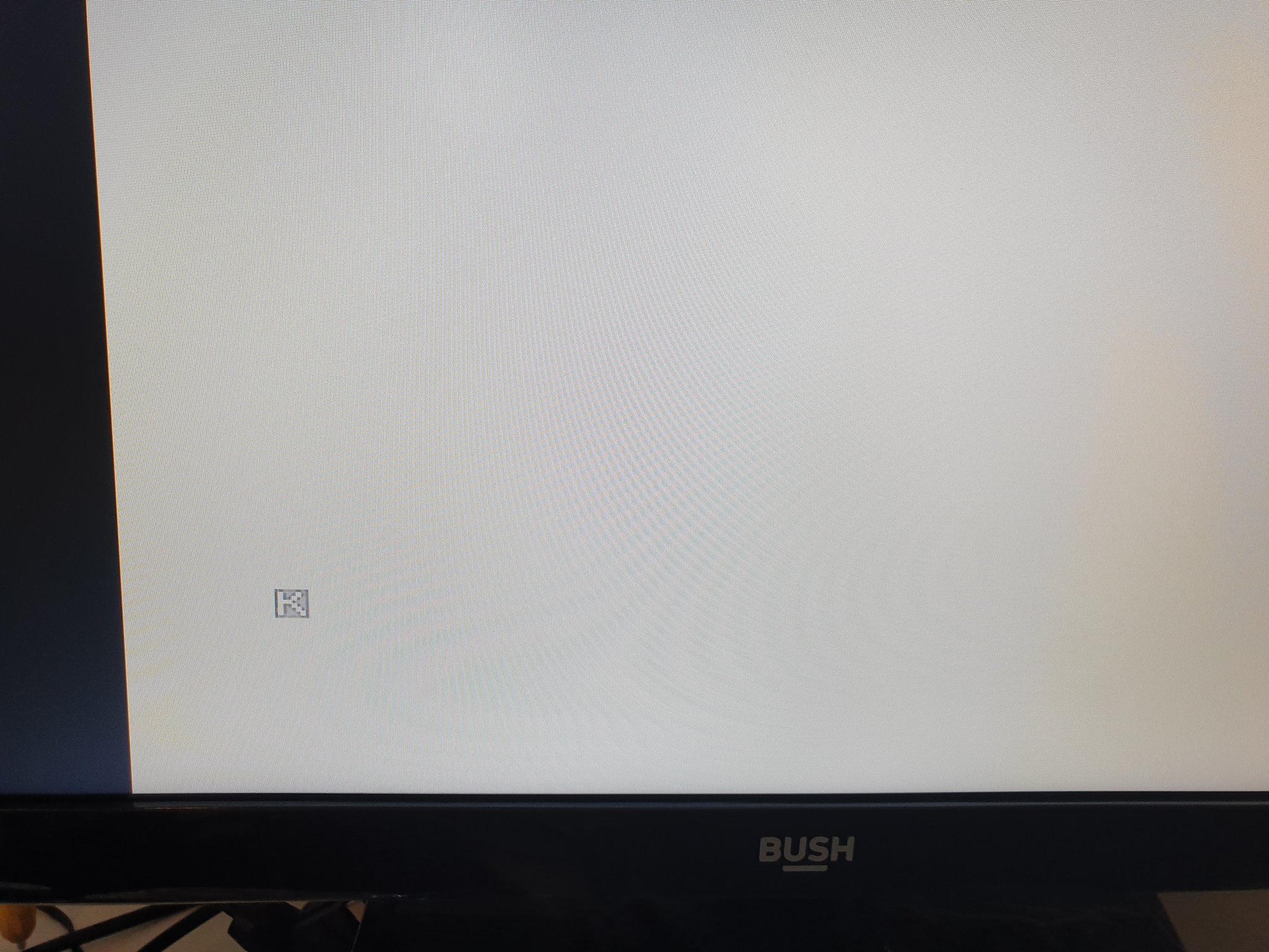
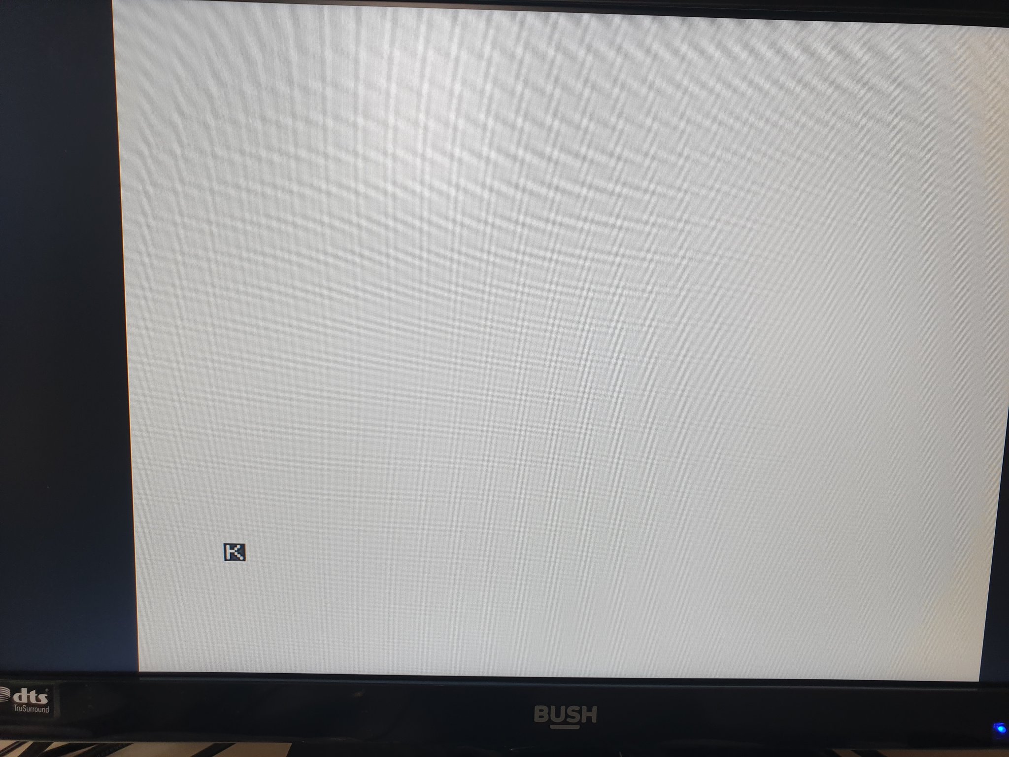
Upon installing the kit, I was pretty disappointed. I had a signal, but it was incredibly washed out on my TV.
This board is a nice version of the common “transistor” mod, which is described nicely here and here - essentially a transistor and a couple of resistors.
The problem must be something to do with the ZX81 itself; so let’s take a look.
The ZX81 Video Signal
Let’s start with a look at the video signal from my ZX81, which is an Issue 3 with ULA version ULA2C184E. The versions will be discussed more later.
This signal was captured directly from pin 16 of the ULA, which is responsible for the signal that is fed into the RF modulator. The ULA emits a composite PAL signal, which the modulator turns into an RF signal that the common TVs of the day would display.
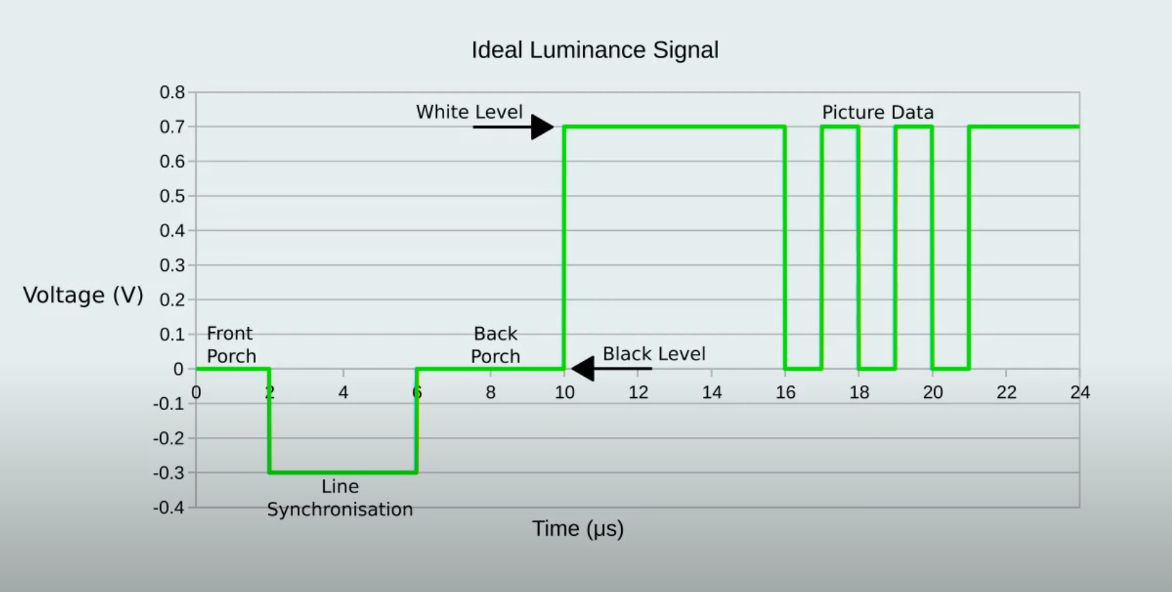
To understand this you need to get into how composite video works. I’ve been studying this for another project, so will highlight the points of interest:
- Every scanline lasts 64us
- Every scanline (that’s not vsync) starts with a sync pulse from its high level (~0.3v) to the low level (0v)
- This sync pulse lasts for ~4us
- The sync pulse is followed by a “back porch” signal which is used to establish the low luminance level (aka black)
- The pixel data follows the back porch for the rest of the scanline
- There should be a 2us “front porch” at the end of the signal which is at sync high
- It is “standard” for the entire signal to be ~1v peak to peak
- The expected difference between black and white is ~0.7v
This is described nicely by the image from zx.zigg.net.
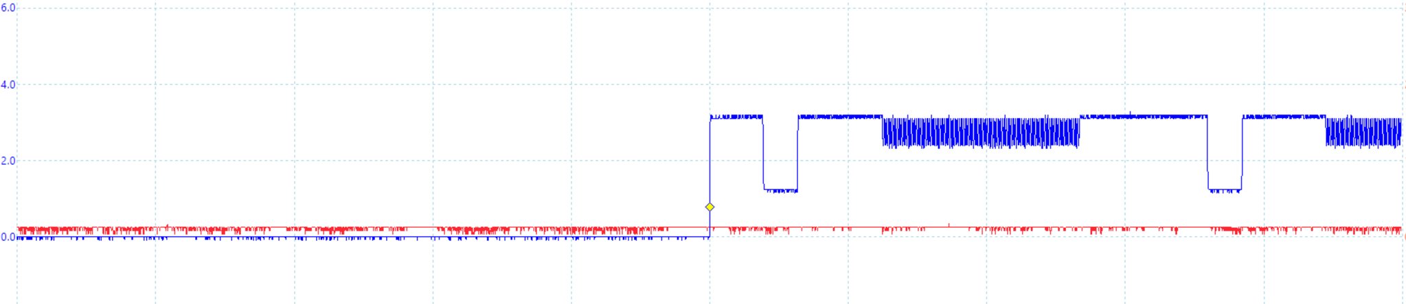
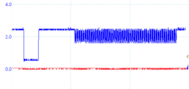
When you look at the signal from my ULA, there’s a few things that stand out.
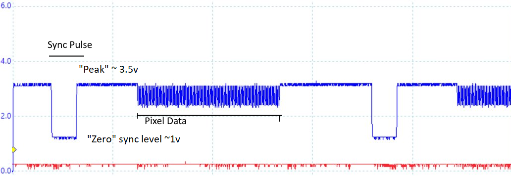
- The “zero” level is about ~1v
- The black voltage level is about ~2.5v
- The white voltage level is about ~3.5v
- The voltage range is ~2.5v
- There is no back porch signal
The difference between white and black is ~1v.
There’s clearly a few things wrong with this signal.
ZX81 Transistor mod analysis
Let’s have a look at what the transistor mod from TFW8Bit did to the signal:
- The “zero” level is now ~0.5v
- The black voltage is now ~1.8v
- The white voltage is now ~2.5v
- The voltage range is about ~2v
So we’ve lowered the voltages and brought the difference between black and white to ~0.7v, which is what the standard expects.
Here’s a gif of what the transistor mod is doing if I simulate a very crude sync pulse straight to white (eg: no pixel burst).
You can view / play with this on the excellent Falstad circuit simulator.
This circuit does roughly what we observed on the scope.
I believe that this mod is suitable for the ULA2C210E, but not for ULA2C184E and older, which have the back porch issue.
The Back Porch Problem
The problem we have is that the TV can’t tell what “black” is because the signal jumps straight to white.
It is typical for this problem to manifest itself as a completely black screen, however on my TV and at least one more person I know it results in the washed out white picture.
What we need to do to fix my issue is to introduce a back porch to the signal. This means that the signal needs to return to it’s high sync level for a period of approximately 8us before rising to the high (white) level.
There are three modifications that I know of that add this:
I have no experience with ZXVid, but it’s on the higher end of the price scale (£30) and there’s no available circuit diagram to discuss. Take a look at the fitting instructions to decide if this is something you want to explore yourself.
zx.zigg.net Video Conditioning
I recommend you go watch the excellent video on how the zx.zigg.net circuit works.
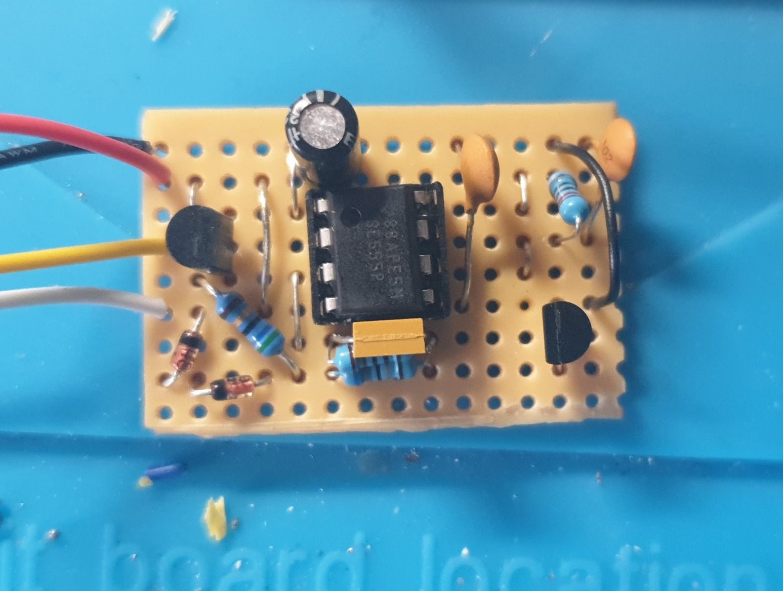
Following this, you can read the document he produced on how do build the 555-based circuit.
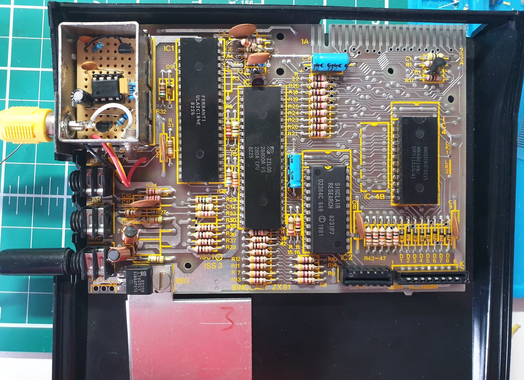
I built the circuit on stripboard…
And it fits nicely inside the modulator can:
It really does make a stunning picture:
The video does a great job of explaining how it all works, but I thought I’d plug it all into Falstad and watch how it operates.
Let’s take a look at the outputs a bit more:
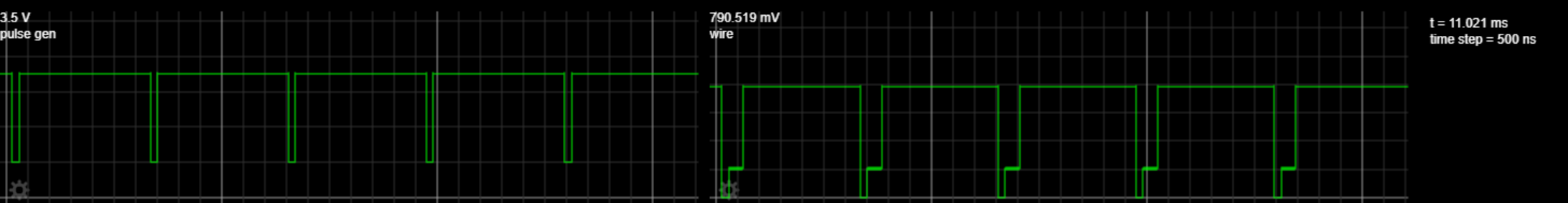
We can clearly see the ~8us back porch injected in there directly after the sync pulse is pulled high.
I won’t detail how it works, as this is explained far better than I can in the original video. But in essence, it uses a 555 timer in a monostable configuration to activate a transistor which momentarily pulls down the output voltage of the video signal, generating the back porch.
On Falstad, at least, the voltage range of the whole signal is significantly decreased to around ~0.8v, with “white” being ~0.8v, black being ~0.2v and sync low being 0v. This puts the signal pretty much bang into expected “perfect” range.
ZX8-CCB Video Conditioning
The ZX8-CCB is an affordable circuit that does what the Zigg circuit does, but also allows for the picture to be inverted.
The circuit diagram is available, but is designed around low-voltage SMD components.
I have built one on stripboard, which will be subject for another post - but let’s have a look at how it works in Falstad.
And the signal output:
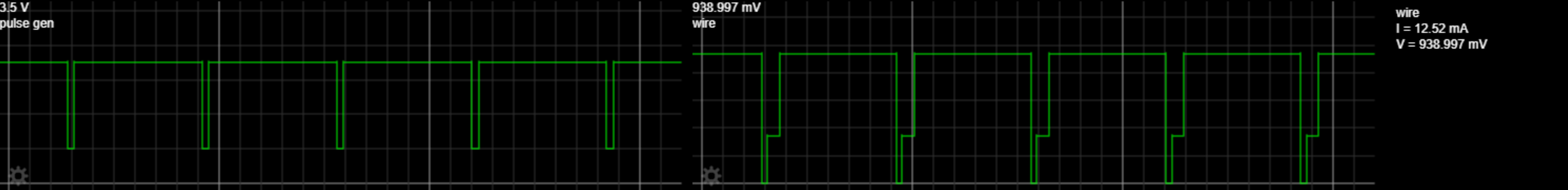
The main things to note from the Falstad sim:
- There is a back porch of ~6us generated
- The “white” level is ~0.94v
- The “black” level is ~0.34v
- The “zero” level is 0v
It is very close to being perfect, although the simulated back porch is a touch too short.
It’s worth noting that there’s a couple of quirks with the Falstad tool, which meant my logic gates use levels of 2.7v instead of 3.3v, but it’s not enough to throw out any conclusions.
ZX8-CCB Analysis
I find the original schematic drawing of the ZX8-CCB a little confusing as it has all the connections. I redrew it here for discussion.
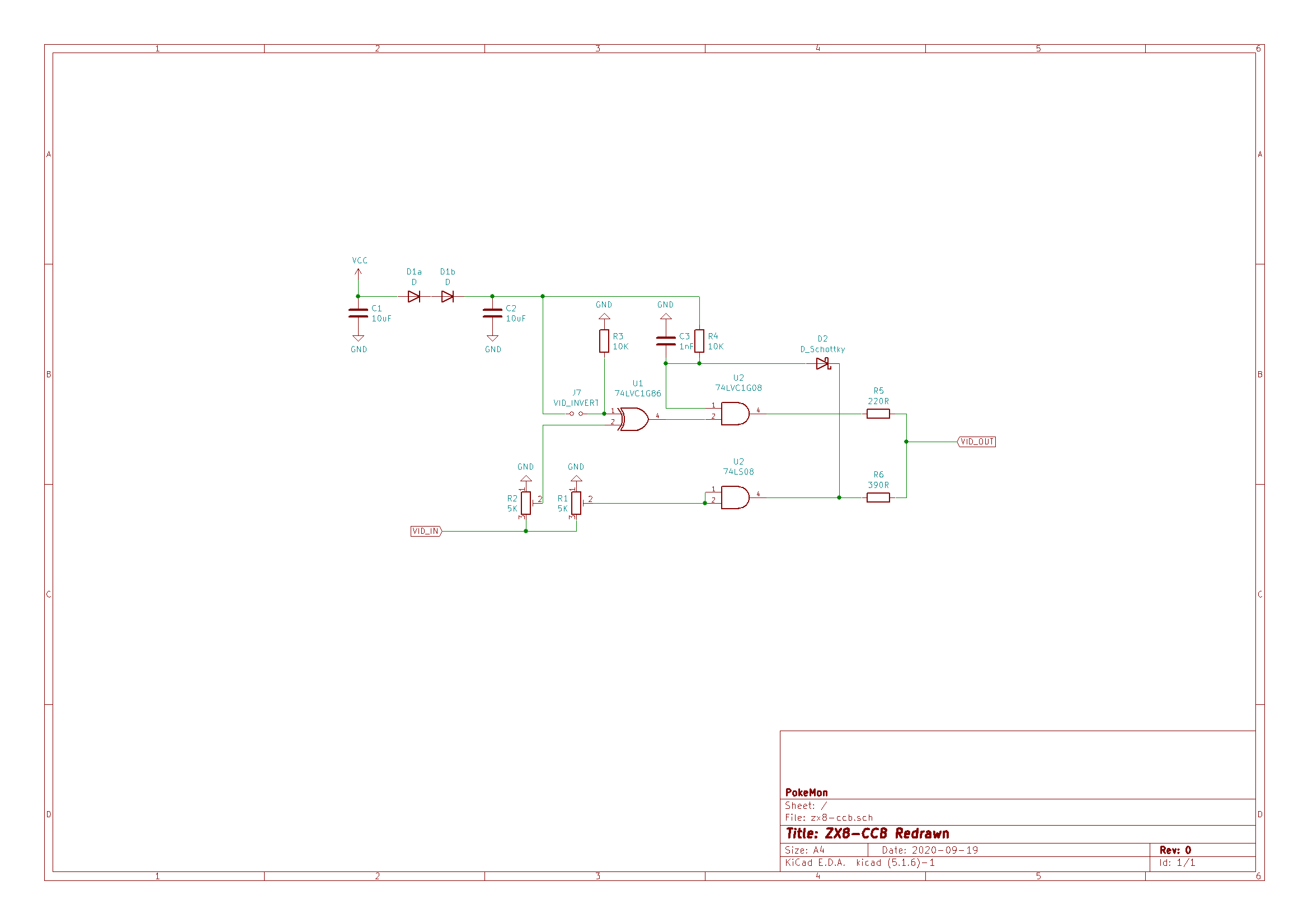
The main points of note:
- R1 and R2 trimmers “separate” the original signal into Sync and Pixels respectively
- The XOR circuit (U1) that takes the pixel data from R2 is enabled by the J7 jumper; this inverts the signal by pulling the colour “high” and then flipping back to white when the screen has a pixel set
- The AND gate at U2 has its two inputs bridged and connected to R1. This has the basic effect of “boosting” the sync pulse to the voltage to logic high of the IC. As this is a LV CMOS chip, it will be 3.3v.
- The back porch is generated by the combination of C3/R4, the Schottky Diode in D3 and the AND gate at U2.
- The remaining resistors are used to combine the two signals into the correct 0.3v/0.7v proportions ready for output.
Let’s take a look at the back porch generation part. With the help of Falstad we can pause the simulation and see what is happening.
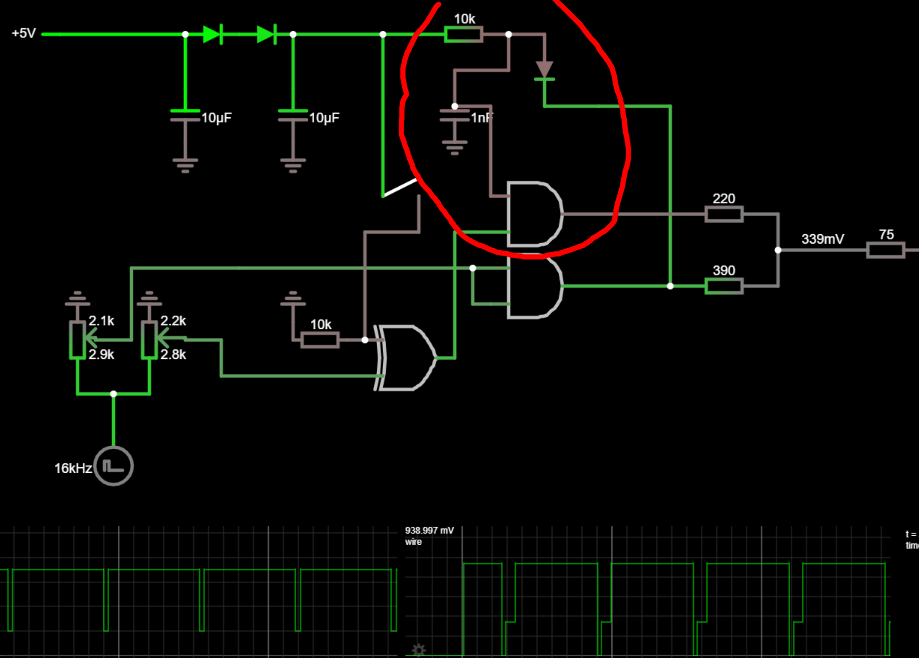
The AND gate at U2 is active when it is under power and is receiving the pixel signal from the trimmer at R2. The first gate is usually pulled high by the pullup resistor at R3, however the clever bit is the use of the capacitor at C3.
At the point where the ZX81 video signal transitions from sync low to the white signal, the capacitor is begins to charge. This acts to keep the first AND input low for few microseconds until the capacitor is charged. This has the effect of momentarily disrupting the Pixel signal, as the AND gate that controls it into into the final output is switched off until the capacitor charges. What this essentially means is that only the Sync line is let through, creating a back porch.
It’s a clever use of logic and an RC circuit to hold a specific part of the signal low.
Wrapping up
The three circuits we examined above each aim to achieve the same goal, with the exception of the simple transistor mod not injecting a back porch.
The zx.zigg.net circuit and ZX8-CCB achieve similar results in different ways and it was fun “figuring out” how these worked overall.
If your ULA doesn’t generate a back porch, then you really should use one of these two circuits to get a nice picture from your ZX81. If you’re lucky enough to have a newer ULA, then you should get by with just the transistor mod - either as a kit or built yourself.
As mentioned before, I have recreated the ZX8-CCB on a breadboard and stripboard; I’ll post about that in the future.
Until next time.